The UART (Universal Asynchronous Receiver-Transmitter) is a communication protocol used by the XBee 3 BLU devices to transmit and receive data over a serial connection. It allows for efficient, full-duplex communication between the XBee and other devices like microcontrollers or computers.
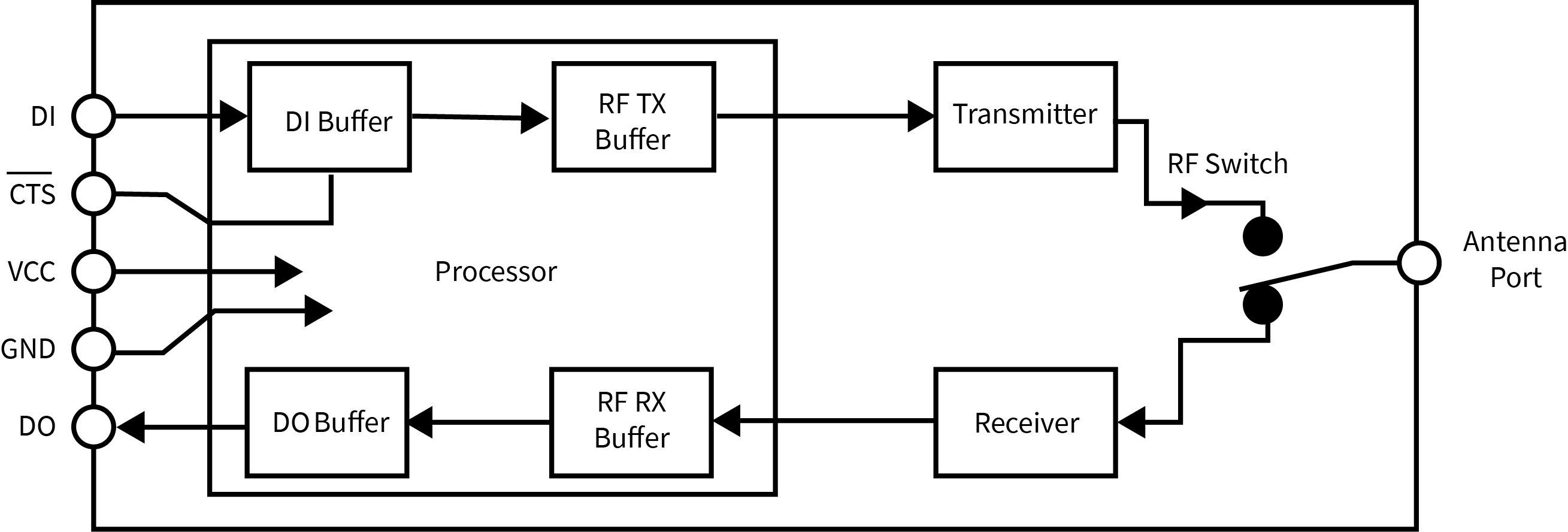
Devices that have a UART interface connect directly to the pins of the XBee 3 BLU as shown in the following figure. The figure shows system data flow in a UART-interfaced environment. Low-asserted signals have a horizontal line over the signal name.

Serial data
The XBee 3 BLU device sends data to the UART as asynchronous serial signals. When the device is not transmitting data, the signals should idle high.
For serial communication to occur, you must configure the UART of both devices (the microcontroller and the XBee 3 BLU) with compatible settings for the baud rate, parity, start bits, stop bits, and data bits.
Each data byte consists of a start bit (low), 8 data bits (least significant bit first) and a stop bit (high). The following diagram illustrates the serial bit pattern of data passing through the device. The diagram shows UART data packet 0x1F (decimal number 31) as transmitted through the device.

You can configure the UART baud rate, parity, and stop bits settings on the device with the BD, NB, and SB commands respectively. For more information, see UART interface commands.
| For more information on how to configure settings on the XBee 3 BLU, see Change device settings. |
Flow control
The XBee 3 BLU manages separate buffers to handle both serial and Bluetooth data.
-
The serial receive buffer stores incoming serial data until the device processes it
-
The serial transmit buffer holds Bluetoon data received over the RF link until it is ready to be sent out through the serial port.
To manage flow control, you can configure the Clear-to-Send (CTS) and Request-to-Send (RTS) settings:
The following figure illustrates how the device buffers accumulate and process incoming serial data.

CTS flow control
When you enable CTS (Clear-to-send) flow control using D7 (DIO7/CTS Configuration), the device de-asserts the CTS line (sets it high) if the serial receive buffer exceeds a threshold (FT bytes).
This signals the host to pause sending data.
CTS is reasserted once the buffer clears below the threshold, which can be adjusted using FT (Flow Control Threshold).
RTS flow control
By setting D6 (DIO6/RTS Configuration) to enable RTS flow control, the device only transmits data from the serial transmit buffer out the DOUT pin when RTS is asserted (low). Prolonged de-assertion of RTS may cause the serial transmit buffer to fill, and any RF data packets that don’t fit into the buffer completely will be discarded.
If RTS is de-asserted while data is still being transmitted, the device may send up to five additional characters before stopping.


