This section walks you through the steps required to assemble and disassemble the hardware components of your kit.
| For more information about the development board included in the kit, see the XBIB-C development board documentation. |
Plug in the XBee module
Follow these steps to connect a XBee 3 BLU device to a XBIB-C development board:
-
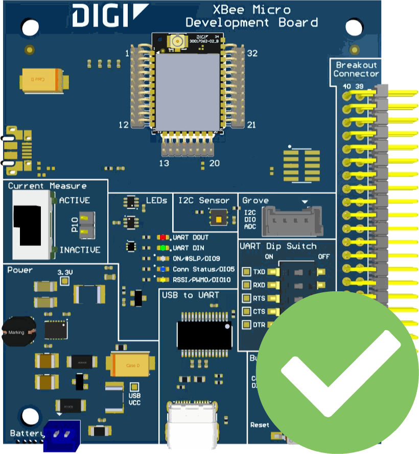
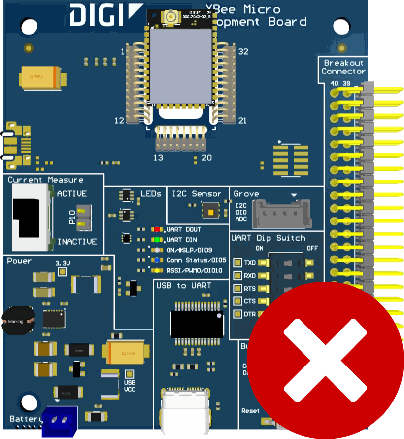
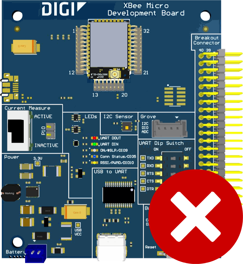
Plug one XBee 3 BLU module into the XBIB-C development board.
Make sure the XBIB-C development board is NOT powered (either by the USB type-C or a battery) when you plug in the XBee 3 BLU module. Align all XBee pins with the spring header and carefully push the module until it is hooked to the board.


-
XBIB-C development board requires a slight modification to enable the XBee 3 BLU device to access the I2C sensor:
-
Connect one end of the test cable to pin 24 of the Breakout connector within the XBIB-C development board and the other end to pin 36:

-
-
Once the XBee 3 BLU module is plugged into the XBIB-C development board (and not before), connect the board to your computer using the USB type-C cables provided.
-
Verify the RSSI (orange LED) is solid.
How to unplug an XBee device
To disconnect your XBee 3 BLU device from the XBIB-C development board:
-
Disconnect the USB type-C cable (or the battery) from the board so it is not powered.
-
Remove the XBee 3 BLU device from the board socket by pressing the device gently through the hole on the back of the board, being careful not to bend any pins.
Make sure the XBIB-C development board is NOT powered when you remove the XBee device.


