The defining characteristic of a real-time (RT) system is that it reacts to an external event within a defined time frame. For example, an automobile airbag must deploy within a very small window of time to be effective, and an automated assembly line component must keep time with the rest of the manufacturing process. Responding late to such events due to heavy system load is not an option.
Several configurations and mechanisms are involved in initiating the deterministic response times of a real-time system, including latency requirements, inter-core communication, hardware resource sharing, unified life cycle management, and unified building and deployment.
| Real-time does not mean a system is faster; it means its maximum response time (or latency) to an event is predictable. |
PREEMPT_RT Linux
Preemption in real-time system refers to temporarily interrupting an event so a higher-priority event can be executed. PREEMPT_RT is a set of patches for the Linux kernel that implement RT capabilities by making the kernel fully preemptible and allowing the scheduler to access execution contexts. Some portions of the kernel such as entry code, the scheduler itself, and low-level interrupt handling remain non-preemptible.
For more information, refer to https://wiki.linuxfoundation.org/realtime/documentation/start.
Enable real-time support in Digi Embedded Yocto
RT support in Digi Embedded Yocto:
-
Applies the PREEMPT_RT kernel patch
-
Applies STM32MP15-specific RT patches
-
Enables RT-specific kernel configuration options
-
Adds RT test tools to the root file system
| Enabling real-time support in Digi Embedded Yocto has implications on prioritization and performance, and does not come without a cost to the system. Digi recommends you perform extensive testing to weigh the costs and benefits and make sure the system fulfills your real-time requirements under worst-case conditions. |
-
To enable RT support in Digi Embedded Yocto, edit your project’s
conf/local.conffile and add the following line:conf/local.confDISTRO_FEATURES:append = " rt"Note the required white space when appending a value to an array variable using the :appendoverride syntax. -
Build the image. For example,
dey-image-webkit:$ bitbake dey-image-webkitBitbaking an image recipe implies downloading and building the source code of all the recipes that form part of the root file system, which takes several hours the first time. Some source code repositories, such as the Linux kernel, represent a large download that might time out and make your build process fail. If this happens, run the following command to just fetch the source code of the offending recipe separately (to dedicate all CPU resources to it):
$ bitbake -k --runall=fetch <image-recipe>When this task finishes successfully (you may need several retries), you can proceed to build your image recipe. Do the same with any recipe that fails with a timeout during the fetch operation.
See Build images and Update firmware to program the real-time images to your target.
-
To verify that the booted kernel includes RT support, use the following command on the target console:
# uname -a
Linux ccmp15-dvk 5.15-xxx-rt65-dey #1 PREEMPT_RT Wed May 8 07:45:21 UTC 2024 armv7l GNU/Linux
Note the
PREEMPT_RTlabel on the kernel tag line.
Benchmarking tools
When RT support is enabled, Digi Embedded Yocto includes the rt-tests suite, which contains, among others, the following tools to support validation and testing.
-
Cyclictest is a benchmarking tool used to measure the real-time performance of a Linux system. It is commonly employed in the context of evaluating the latency and responsiveness of systems running with real-time kernels, such as those using the PREEMPT-RT patches. For more information on the cyclictest tool, refer to the Cyclictest documentation.
-
hwlatdetect is a program that detects latency caused by hardware or firmware running on a Linux system. For more information on hwladetect, refer to https://manpages.ubuntu.com/manpages/focal/en/man8/hwlatdetect.8.html.
Approximating system load
| Real-time system tests should be performed under worst-case conditions. On the sample benchmarking tests below, Digi used the following factors to load the system and generate that worst case. You must set up your own worst-case test conditions. |
Three simultaneous tests approximate load on a system:
-
CoreMark: CoreMark is a benchmark designed by the Embedded Microprocessor Benchmark Consortium (EEMBC) to specifically evaluate the performance of central processing units (CPUs) in embedded systems. It stresses the system by executing a variety of operations that simulate typical workloads found in embedded applications.
-
Ping flood: A ping flood can be used as a method to stress test a network or system by deliberately overwhelming it with ICMP Echo Request (ping) packets. The purpose of this test is to evaluate how well the system can handle a high volume of network traffic and identify potential performance bottlenecks or vulnerabilities.
-
Graphical desktop: Connecting a desktop via HDMI can increase CPU and GPU usage, as the system must process and transmit high-resolution video and audio signals. This additional workload can lead to higher power consumption and potentially affect system performance during demanding tasks.
Benchmarking tests
Cyclictest
This setup helps evaluate the real-time performance of a system by measuring how consistently high-priority threads can wake up after a specified interval. By using five threads, the command stresses the system more, providing insights into how well the system handles multiple high-priority tasks simultaneously and its overall scheduling and latency characteristics.
This configuration is useful for testing systems that are expected to handle multiple real-time tasks concurrently, ensuring they meet the required performance and timing guarantees.
# cyclictest -p 80 -t5 -m -l 100000
T: 0 ( 1945) P:80 I:1000 C: 100000 Min:     15 Act:   20 Avg:  161 Max:    1982
T: 1 ( 1946) P:80 I:1500 C:  72652 Min:     17 Act:   32 Avg:   33 Max:    1067
T: 2 ( 1947) P:80 I:2000 C:  54471 Min:     17 Act:  643 Avg:  135 Max:    2001
T: 3 ( 1948) P:80 I:2500 C:  43563 Min:     17 Act:   28 Avg:   31 Max:    1061
T: 4 ( 1949) P:80 I:3000 C:  36290 Min:     18 Act:  671 Avg:  186 Max:    1937
This command sets up a cyclic test with the following configuration:
-
Creates five threads (-t5) (number of CPUs x2 + 1)
-
Each thread will have a priority of 80 (-p 80)
-
The memory used by the test process will be locked (-m), preventing it from being swapped out
-
The test will perform 100,000 latency measurements (-l 100000)
Use the --help option to see all the available options for the cyclictest command.
Square signal
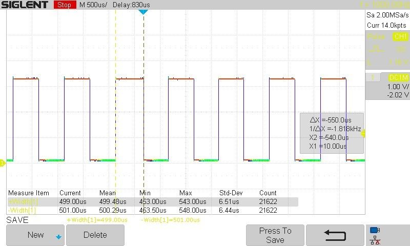
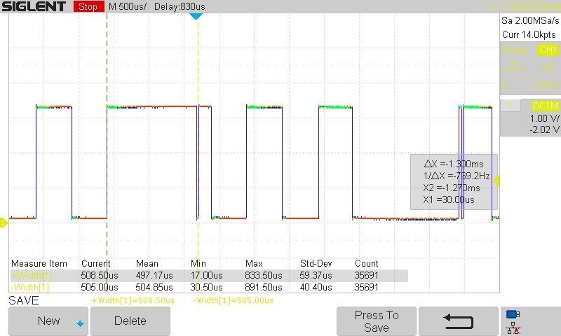
The square signal test measures the timing accuracy and responsiveness of a real-time system by toggling a GPIO pin every 500 microseconds (us) to generate a square wave signal. This test ensures the system maintains precise timing intervals without significant deviation even under heavy load scenarios.
Equipment and tools:
-
Real-time system with Linux
-
Oscilloscope or logic analyzer with statistics measurement capabilities
Test setup:
-
Hardware connection:
-
Connect the designated GPIO pin to an oscilloscope or logic analyzer to monitor the output signal.
-
-
Software configuration:
-
Create a C program that toggles a GPIO pin every 500 us (1 kHz square signal). The program should set real-time priority, lock memory to prevent paging, and use a timer to ensure precise timing. When the timer expires, the GPIO is toggled. Both tests run for one hour with load and without load, and measure the maximum deviation in the wave.
-
Square signal test results are presented as:
-
Minimum positive or negative pulse width of the square signal (Tmin)
-
Maximum positive or negative pulse width of the square signal (Tmax)
Output
The following images show one-shot captures on a non-RT and RT system. While the RT system presents a rather regular square signal, the non-RT system may occasionally generate very large or very short pulses, as the CPU attends other processes during heavy load.
Square signal test on an RT system

Square signal test on a non-RT system

| These images represent example one-time shots taken with the ConnectCore MP13 and are only for illustrative purposes. See Square signal for actual results as measured on the ConnectCore MP15. |
As always when evaluating the real-time response of a system, the important figures to note are the maximum and minimum widths of the pulses across the overall duration of the test. You can get these by looking at the statistics measured by the oscilloscope.
Results
| These results only represent an example of the difference in determinism between an RT and a non-RT system. You must perform your own tests to determine these values in your system. |
Cyclictest
The following results include multi-thread benchmarking test cases both with and without CPU load.
| System load | Value | Non-RT kernel | RT kernel |
|---|---|---|---|
No load |
Max |
2001 us |
195 us |
With load |
Max |
2264 us |
138 us |
Square signal
The square signal test results highlight the differences in timing precision and consistency between RT and non-RT kernels. In an RT kernel, the system maintains regular GPIO toggling intervals with small jitter, showcasing its ability to handle high-priority tasks reliably. In contrast, a non-RT kernel may exhibit greater variability and less predictable timing, underscoring the advantages of RT kernels for applications requiring strict response-time requirements.
The following table represents the minimum and maximum width captured with the oscilloscope during a one-hour test.
| System load | Value | Non-RT kernel | RT kernel |
|---|---|---|---|
No load |
Tmin |
356 us |
440 us |
Tmax |
772 us |
558 us |
|
With load |
Tmin |
226 us |
418 us |
Tmax |
772 us |
582 us |


