

The STM32MP25 processor provides a Digital Camera Memory Interface Pixel Processor (DCMIPP) sourced from a MIPI CSI-2 host controller.
The ConnectCore MP25 Development Kit supports a MIPI CSI camera via a connector composed of two differential data lines, differential clock, reset, and the I2C1 bus.
The BSP includes support for the following cameras:
-
OmniVision OV5640 MIPI camera on 15 pin connector (J30)
-
Sony imx335 MIPI-CSI camera on 22 pin connector (J29)
|
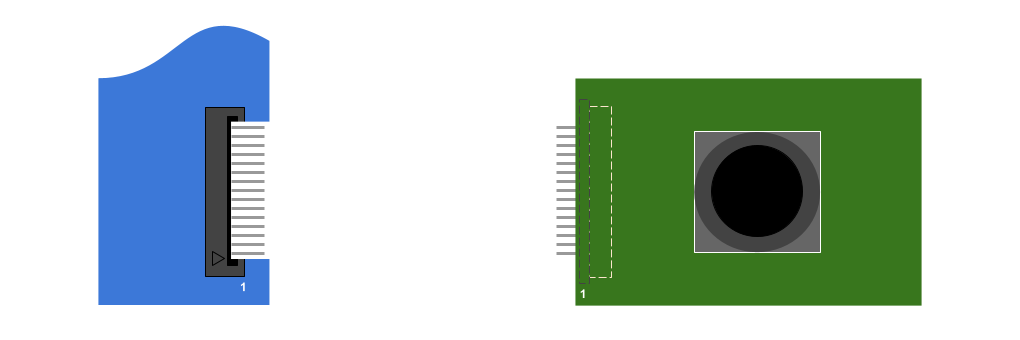
Make sure you use the correct cable to connect the MIPI camera to the ConnectCore MP25 Development Kit. Using the wrong cable may damage the camera. For ConnectCore MP25 Development Kit, use a 15 pin, 1mm pitch FFC cable with contacts on top on both sides. Pin 1 of the ConnectCore MP25 Development Kit connector aligns with pin 1 of the camera connector.
|
Kernel configuration
You can manage the camera driver support and Video4Linux (V4L2) capture driver through the following kernel configuration options:
-
STM32 Digital Camera Memory Interface (DCMI) support (
CONFIG_VIDEO_STM32_DCMI) -
STM32 Digital Camera Memory Interface Pixel Processor (DCMIPP) support (
CONFIG_VIDEO_STM32_DCMIPP) -
STM32 Camera Serial Interface (CSI) support (
CONFIG_VIDEO_STM32_CSI2HOST) -
OmniVision ov5640 camera support (
CONFIG_VIDEO_OV5640) -
Sony IMX335 sensor support (
CONFIG_VIDEO_IMX335)
These options are enabled as modules and built-in on the default ConnectCore MP25 kernel configuration file.
Kernel driver
The drivers for the camera are located at:
| File | Description |
|---|---|
STM32 Digital Camera Memory Interface (DCMI) driver |
|
STM32 Digital Camera Memory Interface Pixel Processor (DCMIPP) driver |
|
STM32 Camera Serial Interface (CSI) support |
|
Omnivision OV5640 sensor driver |
|
Sony IMX335 sensor driver |
Device tree bindings and customization
Common bindings for video receiver and transmitter interfaces are described at Documentation/devicetree/bindings/media/video-interfaces.yaml.
The device tree must contain entries for:
-
The V4L2 capture interface
-
The camera sensor
V4L2 capture interface (DCMIPP)
&csi2host {
	status = "okay";
	ports {
		#address-cells = <1>;
		#size-cells = <0>;
		port@0 {
			reg = <0>;
			csi2host_sink: endpoint {
				remote-endpoint = <&ov5640_mipi_ep>;
				data-lanes = <0 1>;
				bus-type = <4>;
			};
		};
		port@1 {
			reg = <1>;
				csi2host_source: endpoint {
				remote-endpoint = <&dcmipp_0>;
			};
		};
	};
};

&dcmipp {
	status = "okay";
	port {
		dcmipp_0: endpoint {
			remote-endpoint = <&csi2host_source>;
			bus-type = <4>;
		};
	};
};
Omnivision OV5640 camera sensor (I2C1 slave)
&i2c1 {
...
ov5640_mipi: ov5640_mipi@3c {
compatible = "ovti,ov5640";
reg = <0x3c>;
clocks = <&clk_ext_camera>;
clock-names = "xclk";
csi_id = <0>;
DOVDD-supply = <®_3v3_board>;
powerdown-gpios = <&gpiog 7 (GPIO_ACTIVE_LOW | GPIO_PUSH_PULL)>; /* CSI_RESET */
status = "okay";
port {
ov5640_mipi_ep: endpoint {
remote-endpoint = <&csi_sink>;
clock-lanes = <0>;
data-lanes = <1 2>;
link-frequencies = /bits/ 64 <594000000>;
};
};
};
...
};Sony IMX335 camera sensor (I2C1 slave)
Support for Sony IMX335 camera sensor is provided inside an additional device tree overlay located at arch/arm64/boot/dts/digi/ccmp25-dvk_imx335-mipi-csi.dtso
&i2c1 {
...
	imx335: imx335@1a {
		compatible = "sony,imx335";
		reg = <0x1a>;
		clocks = <&clk_ext_camera>;
		reset-gpios = <&gpiog 7 (GPIO_ACTIVE_HIGH | GPIO_PUSH_PULL)>;
		powerdown-gpios = <&gpiof 3 (GPIO_ACTIVE_HIGH | GPIO_PUSH_PULL)>;
		status = "okay";

		port {
			imx335_ep: endpoint {
				remote-endpoint = <&csi_sink>;
				clock-lanes = <0>;
				data-lanes = <1 2>;
				link-frequencies = /bits/ 64 <594000000>;
			};
		};
	};
...
};
Using the camera
Identify the camera capture devices
Camera configuration and operation is divided between several interconnected subdevices, called entities, sharing video data.
You can use the media-ctl tool to obtain the full camera subsystem topology, a list of subdevices, the connections between them, and some additional postprocessing operations that can be performed on the fly such as cropping or downscaling:
# media-ctl -d platform:48030000.dcmipp -p
Media controller API version 6.6.48

Media device information
------------------------
driver          dcmipp
model           DCMIPP MDEV
serial
bus info        platform:48030000.dcmipp
hw revision     0x30
driver version  6.6.48

Device topology
- entity 1: dcmipp_input (4 pads, 5 links, 0 routes)
            type V4L2 subdev subtype Unknown flags 0
            device node name /dev/v4l-subdev0
        pad0: Sink
                [stream:0 fmt:RGB565_2X8_LE/640x480 field:none colorspace:rec709]
                <- "dcmipp_tpg":0 []
                <- "48020000.csi":1 [ENABLED]
        pad1: Source
                [stream:0 fmt:RGB565_2X8_LE/640x480 field:none colorspace:rec709]
                -> "dcmipp_dump_postproc":0 []
        pad2: Source
                [stream:0 fmt:RGB565_2X8_LE/640x480 field:none colorspace:rec709]
                -> "dcmipp_main_isp":0 []
        pad3: Source
                [stream:0 fmt:RGB565_2X8_LE/640x480 field:none colorspace:rec709]
                -> "dcmipp_aux_postproc":0 []
[...]
- entity 18: dcmipp_main_postproc (2 pads, 2 links, 0 routes)
             type V4L2 subdev subtype Unknown flags 0
             device node name /dev/v4l-subdev3
        pad0: Sink
                [stream:0 fmt:RGB888_1X24/640x480@1/30 field:none colorspace:rec709
                 crop.bounds:(0,0)/640x480
                 crop:(0,0)/640x480
                 compose.bounds:(0,0)/640x480
                 compose:(0,0)/640x480]
                <- "dcmipp_main_isp":1 [ENABLED,IMMUTABLE]
        pad1: Source
                [stream:0 fmt:RGB888_1X24/640x480@1/30 field:none colorspace:rec709]
                -> "dcmipp_main_capture":0 [ENABLED,IMMUTABLE]

- entity 21: dcmipp_main_capture (1 pad, 1 link)
             type Node subtype V4L flags 0
             device node name /dev/video3
        pad0: Sink
                <- "dcmipp_main_postproc":1 [ENABLED,IMMUTABLE]
[...]
- entity 69: ov5640 0-003c (1 pad, 1 link, 0 routes)
             type V4L2 subdev subtype Sensor flags 0
             device node name /dev/v4l-subdev7
        pad0: Source
                [stream:0 fmt:UYVY8_1X16/640x480@1/30 field:none colorspace:srgb xfer:srgb ycbcr:601 quantization:full-range
                 crop.bounds:(0,0)/2624x1964
                 crop:(16,14)/2592x1944]
                -> "48020000.csi":0 [ENABLED,IMMUTABLE]
Alternatively, you can create a dot graph using the same tool to have a visual representation of the whole camera subsystem:
# media-ctl -d platform:48030000.dcmipp --print-dot > graph.dotUse your host PC to convert the graph.dot file to a PNG image:
$ dot -Tpng -Nfontname=Roboto -Nfontsize=10 -Efontname=Roboto -Efontsize=10 graph.dot > graph.png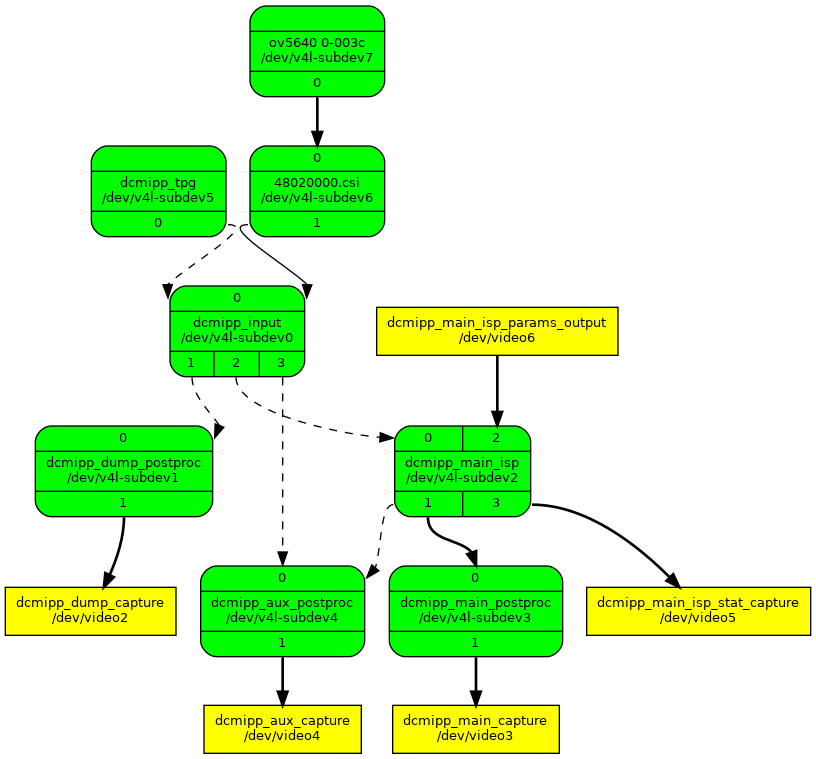
This graph, generated by the media-ctl tool, shows the different video pipes the data can flow through from the camera sensor on the top (source) to the Linux video devices on the bottom (sink).
The camera subsystem creates four video devices, each for a different purpose:
-
/dev/video2is the capture device for the dump pipe. Through the dump pipe, you can read unprocessed video data. -
/dev/video3is the capture device for the main pipe. The main pipe contains most of the processing capabilities of the system, such as scaling, frame skipping, de-Bayering, image correction, color conversion, etc. -
/dev/video4is the capture device for the auxiliary pipe. This pipe can perform some limited processing, like scaling and color conversion. -
/dev/video5is the capture device for statistical data about the image. -
/dev/video6is the input device for injecting ISP block configuration.
Preview a camera image using gstreamer
To get a camera preview:
-
Configure all the nodes in the main pipe for the desired resolution and format (in this example, raw video at 1280x720):
# media-ctl -d platform:48030000.dcmipp --set-v4l2 "'ov5640 0-003c':0[fmt:SBGGR8_1X8/1280x720]" # media-ctl -d platform:48030000.dcmipp --set-v4l2 "'48020000.csi':1[fmt:SBGGR8_1X8/1280x720]" # media-ctl -d platform:48030000.dcmipp -l "'dcmipp_input':2->'dcmipp_main_isp':0[1]" # media-ctl -d platform:48030000.dcmipp --set-v4l2 "'dcmipp_input':2[fmt:SBGGR8_1X8/1280x720]" # media-ctl -d platform:48030000.dcmipp --set-v4l2 "'dcmipp_main_isp':1[fmt:RGB888_1X24/1280x720 field:none]" # media-ctl -d platform:48030000.dcmipp --set-v4l2 "'dcmipp_main_postproc':1[fmt:RGB888_1X24/1280x720]" -
Use gstreamer to capture from videosink
/dev/video3using the selected video format and redirect it to your display:# gst-launch-1.0 v4l2src device=/dev/video3 ! 'video/x-raw, format=RGB16, width=1280, height=720, framerate=(fraction)30/1' ! queue ! autovideosink
Take a picture with the camera using gstreamer
To take a picture:
-
Configure all the nodes in the main pipe for the desired resolution and format (in this example, raw video at 1280x720). Ensure the selected format is supported by the jpegenc plugin of gstreamer:
# media-ctl -d platform:48030000.dcmipp --set-v4l2 "'ov5640 0-003c':0[fmt:SBGGR8_1X8/1280x720]" # media-ctl -d platform:48030000.dcmipp --set-v4l2 "'48020000.csi':1[fmt:SBGGR8_1X8/1280x720]" # media-ctl -d platform:48030000.dcmipp -l "'dcmipp_input':2->'dcmipp_main_isp':0[1]" # media-ctl -d platform:48030000.dcmipp --set-v4l2 "'dcmipp_input':2[fmt:SBGGR8_1X8/1280x720]" # media-ctl -d platform:48030000.dcmipp --set-v4l2 "'dcmipp_main_isp':1[fmt:RGB888_1X24/1280x720 field:none]" # media-ctl -d platform:48030000.dcmipp --set-v4l2 "'dcmipp_main_postproc':1[fmt:YUV8_1X24/1280x720]" -
Use gstreamer to capture from videosink
/dev/video3using the selected video format and encode it as a JPEG picture addingjpegencto the gstreamer pipe:# gst-launch-1.0 v4l2src device=/dev/video3 num-buffers=1 ! 'video/x-raw, format=YUY2, width=1280, height=720, framerate=(fraction)30/1' ! jpegenc ! filesink location=grab-1280x720.jpeg -
Display the captured image:
# weston-image grab-1280x720.jpeg
Record a video with the camera using gstreamer
To record a video:
-
Configure the camera sensor,
stm32_csi2hostanddcmipp_main_ispnodes for the desired resolution and format (in this example, raw video at 1280x720). -
Downscale the frame size using the
dcmipp_main_postprocnode to avoid a penalization in frame rate produced by video processing latency (in this example, to 640x480). Ensure the selected format is supported by the avimux plugin of gstreamer:# media-ctl -d platform:48030000.dcmipp --set-v4l2 "'ov5640 0-003c':0[fmt:SBGGR8_1X8/1280x720]" # media-ctl -d platform:48030000.dcmipp --set-v4l2 "'48020000.csi':1[fmt:SBGGR8_1X8/1280x720]" # media-ctl -d platform:48030000.dcmipp -l "'dcmipp_input':2->'dcmipp_main_isp':0[1]" # media-ctl -d platform:48030000.dcmipp --set-v4l2 "'dcmipp_input':2[fmt:SBGGR8_1X8/1280x720]" # media-ctl -d platform:48030000.dcmipp --set-v4l2 "'dcmipp_main_isp':1[fmt:RGB888_1X24/1280x720 field:none]" # media-ctl -d platform:48030000.dcmipp --set-v4l2 "'dcmipp_main_postproc':1[fmt:YUV8_1X24/1280x720]" -
Use gstreamer to capture several frames from videosink
/dev/video3using the selected video format and encode it as an AVI video addingavimuxto the gstreamer pipe (in this example, capture 150 frames at 30 fps for a 5 second video):# gst-launch-1.0 v4l2src device=/dev/video3 num-buffers=150 ! 'video/x-raw, format=YUY2, width=1280, height=720, framerate=(fraction)30/1' ! avimux ! filesink location=output.avi -
Play back the recorded video:
# gst-play-1.0 output.avi
Advanced camera configurations
List allowed configurations for each subdevice
To capture video data from the camera, you must configure every subdevice in the pipe from top to bottom to manage the video data using certain format and frame size. Some subdevices are able to convert the video format on the fly and therefore use a different format on their input than on their output. You can rely on the graph to understand which subdevice should be used for each element of the pipe, and which pad corresponds to their input or output.
For example, list the video output format of the first node of the graph (at the top), /dev/v4l-subdev7, which corresponds to the OV5640 camera sensor:
# v4l2-ctl -d /dev/v4l-subdev7 --list-subdev-mbus-codes 0
ioctl: VIDIOC_SUBDEV_ENUM_MBUS_CODE (pad=0,stream=0)
        0x4001: MEDIA_BUS_FMT_JPEG_1X8
        0x200f: MEDIA_BUS_FMT_UYVY8_1X16
        0x2011: MEDIA_BUS_FMT_YUYV8_1X16
        0x1017: MEDIA_BUS_FMT_RGB565_1X16
        0x1013: MEDIA_BUS_FMT_BGR888_1X24
        0x3001: MEDIA_BUS_FMT_SBGGR8_1X8
        0x3013: MEDIA_BUS_FMT_SGBRG8_1X8
        0x3002: MEDIA_BUS_FMT_SGRBG8_1X8
        0x3014: MEDIA_BUS_FMT_SRGGB8_1X8
Select one, for example MEDIA_BUS_FMT_RGB565_1X16, and list the available frame sizes for that format:
# v4l2-ctl -d /dev/v4l-subdev7 --list-subdev-framesizes pad=0,code=MEDIA_BUS_FMT_RGB565_1X16
ioctl: VIDIOC_SUBDEV_ENUM_FRAME_SIZE (pad=0,stream=0)
        Size Range: 160x120 - 160x120
        Size Range: 176x144 - 176x144
        Size Range: 320x240 - 320x240
        Size Range: 640x480 - 640x480
        Size Range: 720x480 - 720x480
        Size Range: 720x576 - 720x576
        Size Range: 1024x768 - 1024x768
        Size Range: 1280x720 - 1280x720
        Size Range: 1920x1080 - 1920x1080
        Size Range: 2592x1944 - 2592x1944
You can list the available format for the rest of the subdevices using similar commands.
For example, you can see the /dev/v4l-subdev2 node, which corresponds to the main image processor, accepts many possible video formats on its input (pad 0) but is only capable of streaming on two 24-bit video raw formats on its output (pad 1):
# v4l2-ctl -d /dev/v4l-subdev2 --list-subdev-mbus-codes 0
ioctl: VIDIOC_SUBDEV_ENUM_MBUS_CODE (pad=0,stream=0)
        0x1008: MEDIA_BUS_FMT_RGB565_2X8_LE
        0x1017: MEDIA_BUS_FMT_RGB565_1X16
        0x101c: MEDIA_BUS_FMT_RGB888_3X8
        0x100a: MEDIA_BUS_FMT_RGB888_1X24
        0x2008: MEDIA_BUS_FMT_YUYV8_2X8
        0x200f: MEDIA_BUS_FMT_UYVY8_1X16
        0x2001: MEDIA_BUS_FMT_Y8_1X8
        0x200a: MEDIA_BUS_FMT_Y10_1X10
        0x2013: MEDIA_BUS_FMT_Y12_1X12
        0x202d: MEDIA_BUS_FMT_Y14_1X14
        0x3001: MEDIA_BUS_FMT_SBGGR8_1X8
        0x3013: MEDIA_BUS_FMT_SGBRG8_1X8
        0x3002: MEDIA_BUS_FMT_SGRBG8_1X8
        0x3014: MEDIA_BUS_FMT_SRGGB8_1X8
        0x3007: MEDIA_BUS_FMT_SBGGR10_1X10
        0x300e: MEDIA_BUS_FMT_SGBRG10_1X10
        0x300a: MEDIA_BUS_FMT_SGRBG10_1X10
        0x300f: MEDIA_BUS_FMT_SRGGB10_1X10
        0x3008: MEDIA_BUS_FMT_SBGGR12_1X12
        0x3010: MEDIA_BUS_FMT_SGBRG12_1X12
        0x3011: MEDIA_BUS_FMT_SGRBG12_1X12
        0x3012: MEDIA_BUS_FMT_SRGGB12_1X12
        0x3019: MEDIA_BUS_FMT_SBGGR14_1X14
        0x301a: MEDIA_BUS_FMT_SGBRG14_1X14
        0x301b: MEDIA_BUS_FMT_SGRBG14_1X14
        0x301c: MEDIA_BUS_FMT_SRGGB14_1X14
        0x301d: MEDIA_BUS_FMT_SBGGR16_1X16
        0x301e: MEDIA_BUS_FMT_SGBRG16_1X16
        0x301f: MEDIA_BUS_FMT_SGRBG16_1X16
        0x3020: MEDIA_BUS_FMT_SRGGB16_1X16
# v4l2-ctl -d /dev/v4l-subdev2 --list-subdev-mbus-codes 1
ioctl: VIDIOC_SUBDEV_ENUM_MBUS_CODE (pad=1,stream=0)
        0x100a: MEDIA_BUS_FMT_RGB888_1X24
        0x2025: MEDIA_BUS_FMT_YUV8_1X24
Set configurations for a subdevice
You can use the media-ctl tool to set configurations for any media entity in the graph:
# media-ctl -d platform:48030000.dcmipp --set-v4l2 "'<entity-name>':<pad>[<settings>]" -vConfigurable settings include:
-
Video format:
fmt:<format-code>/<frame-size> -
Video field:
field:<field-name> -
Video colorspace:
colorspace:<colorspace-name> -
Crop processing:
crop:(<left>,<top>)/<frame-size> -
Scale processing:
compose:(<left>,<top>)/<frame-size>
For example, to configure the camera sensor (which is associated with the ov5640 0-003c media entity in the graph) to stream video with MEDIA_BUS_FMT_RGB565_1X16 format and 1280x720 frame size, you must set the media entity output pad (0) fmt property with the following command:
# media-ctl -d platform:48030000.dcmipp --set-v4l2 "'ov5640 0-003c':0[fmt:RGB565_1X16/1280x720]" -vIf, for example, later down the pipe, you want to downscale the video to a 640x480 frame size, configure the dcmipp_main_postproc media entity input pad (0) to perform a compose operation to that size with the following command:
# media-ctl -d platform:48030000.dcmipp --set-v4l2 "'dcmipp_main_postproc':0[compose:(0,0)/640x480]" -vGet and set additional controls
Some video subdevices have additional controls you can set.
Use the following command to get the list of available controls:
# v4l2-ctl -d <V4L2 subdevice> -LUse the following command to set a control with a new value:
# v4l2-ctl -d <V4L2 subdevice> --set-ctrl <control-name>=<control-value>For example, list the available controls of subdevice /dev/v4l-subdev7, which corresponds to the OV5640 camera sensor:
# v4l2-ctl -d /dev/v4l-subdev7 -L

User Controls

                       contrast 0x00980901 (int)    : min=0 max=255 step=1 default=0 value=0 flags=slider
                     saturation 0x00980902 (int)    : min=0 max=255 step=1 default=64 value=64 flags=slider
                            hue 0x00980903 (int)    : min=0 max=359 step=1 default=0 value=0 flags=slider
        white_balance_automatic 0x0098090c (bool)   : default=1 value=1 flags=update
                    red_balance 0x0098090e (int)    : min=0 max=4095 step=1 default=0 value=0 flags=inactive, slider
                   blue_balance 0x0098090f (int)    : min=0 max=4095 step=1 default=0 value=0 flags=inactive, slider
                       exposure 0x00980911 (int)    : min=0 max=1276 step=1 default=0 value=0 flags=inactive, volatile
                 gain_automatic 0x00980912 (bool)   : default=1 value=1 flags=update
                horizontal_flip 0x00980914 (bool)   : default=0 value=0
                  vertical_flip 0x00980915 (bool)   : default=0 value=0
           power_line_frequency 0x00980918 (menu)   : min=0 max=3 default=1 value=1 (50 Hz)
                                0: Disabled
                                1: 50 Hz
                                2: 60 Hz
                                3: Auto

Camera Controls

                  auto_exposure 0x009a0901 (menu)   : min=0 max=1 default=0 value=0 (Auto Mode) flags=update
                                0: Auto Mode
                                1: Manual Mode

Image Source Controls

              vertical_blanking 0x009e0901 (int)    : min=24 max=2655 step=1 default=560 value=560
            horizontal_blanking 0x009e0902 (int)    : min=320 max=320 step=1 default=320 value=320 flags=read-only
                  analogue_gain 0x009e0903 (int)    : min=0 max=1023 step=1 default=0 value=0 flags=inactive, volatile

Image Processing Controls

                 link_frequency 0x009f0901 (intmenu): min=0 max=22 default=13 value=18 (248000000 0xec82e00) flags=read-only
                                0: 992000000 (0x3b20b800)
                                1: 888000000 (0x34edce00)
                                2: 768000000 (0x2dc6c000)
                                3: 744000000 (0x2c588a00)
                                4: 672000000 (0x280de800)
                                5: 672000000 (0x280de800)
                                6: 592000000 (0x23493400)
                                7: 592000000 (0x23493400)
                                8: 576000000 (0x22551000)
                                9: 576000000 (0x22551000)
                                10: 496000000 (0x1d905c00)
                                11: 496000000 (0x1d905c00)
                                12: 384000000 (0x16e36000)
                                13: 384000000 (0x16e36000)
                                14: 384000000 (0x16e36000)
                                15: 336000000 (0x1406f400)
                                16: 296000000 (0x11a49a00)
                                17: 288000000 (0x112a8800)
                                18: 248000000 (0xec82e00)
                                19: 192000000 (0xb71b000)
                                20: 192000000 (0xb71b000)
                                21: 192000000 (0xb71b000)
                                22: 96000000 (0x5b8d800)
                     pixel_rate 0x009f0902 (int64)  : min=48000000 max=168000000 step=1 default=48000000 value=124000000 flags=read-only
                   test_pattern 0x009f0903 (menu)   : min=0 max=4 default=0 value=0 (Disabled)
                                0: Disabled
                                1: Color bars
                                2: Color bars w/ rolling bar
                                3: Color squares
                                4: Color squares w/ rolling bar
Configure, for example, an horizontal flip of the image in the camera sensor. This is performed by the camera sensor itself and does not require later postprocessing:
# v4l2-ctl -d /dev/v4l-subdev7 --set-ctrl horizontal_flip=1List allowed formats for each video device
Run the following v4l2-ctl command to get the available video formats of the dump, main and aux video devices, which you will later use to capture the frames using gst-launch-1.0 tool:
# v4l2-ctl -d /dev/video2 --list-formats
ioctl: VIDIOC_ENUM_FMT
        Type: Video Capture

        [0]: 'RGBP' (16-bit RGB 5-6-5)
        [1]: 'RGB3' (24-bit RGB 8-8-8)
        [2]: 'YUYV' (YUYV 4:2:2)
        [3]: 'YVYU' (YVYU 4:2:2)
        [4]: 'UYVY' (UYVY 4:2:2)
        [5]: 'VYUY' (VYUY 4:2:2)
        [6]: 'GREY' (8-bit Greyscale)
        [7]: 'Y10 ' (10-bit Greyscale)
        [8]: 'Y12 ' (12-bit Greyscale)
        [9]: 'Y14 ' (14-bit Greyscale)
        [10]: 'BA81' (8-bit Bayer BGBG/GRGR)
        [11]: 'GBRG' (8-bit Bayer GBGB/RGRG)
        [12]: 'GRBG' (8-bit Bayer GRGR/BGBG)
        [13]: 'RGGB' (8-bit Bayer RGRG/GBGB)
        [14]: 'BG10' (10-bit Bayer BGBG/GRGR)
        [15]: 'GB10' (10-bit Bayer GBGB/RGRG)
        [16]: 'BA10' (10-bit Bayer GRGR/BGBG)
        [17]: 'RG10' (10-bit Bayer RGRG/GBGB)
        [18]: 'BG12' (12-bit Bayer BGBG/GRGR)
        [19]: 'GB12' (12-bit Bayer GBGB/RGRG)
        [20]: 'BA12' (12-bit Bayer GRGR/BGBG)
        [21]: 'RG12' (12-bit Bayer RGRG/GBGB)
        [22]: 'BG14' (14-bit Bayer BGBG/GRGR)
        [23]: 'GB14' (14-bit Bayer GBGB/RGRG)
        [24]: 'GR14' (14-bit Bayer GRGR/BGBG)
        [25]: 'RG14' (14-bit Bayer RGRG/GBGB)
        [26]: 'JPEG' (JFIF JPEG, compressed)

# v4l2-ctl -d /dev/video3 --list-formats
ioctl: VIDIOC_ENUM_FMT
        Type: Video Capture

        [0]: 'RGBP' (16-bit RGB 5-6-5)
        [1]: 'YUYV' (YUYV 4:2:2)
        [2]: 'YVYU' (YVYU 4:2:2)
        [3]: 'UYVY' (UYVY 4:2:2)
        [4]: 'VYUY' (VYUY 4:2:2)
        [5]: 'GREY' (8-bit Greyscale)
        [6]: 'RGB3' (24-bit RGB 8-8-8)
        [7]: 'BGR3' (24-bit BGR 8-8-8)
        [8]: 'BA24' (32-bit ARGB 8-8-8-8)
        [9]: 'AR24' (32-bit BGRA 8-8-8-8)
        [10]: 'AB24' (32-bit RGBA 8-8-8-8)
        [11]: 'RA24' (32-bit ABGR 8-8-8-8)
        [12]: 'NV12' (Y/UV 4:2:0)
        [13]: 'NV21' (Y/VU 4:2:0)
        [14]: 'NV16' (Y/UV 4:2:2)
        [15]: 'NV61' (Y/VU 4:2:2)
        [16]: 'YU12' (Planar YUV 4:2:0)
        [17]: 'YV12' (Planar YVU 4:2:0)

# v4l2-ctl -d /dev/video4 --list-formats
ioctl: VIDIOC_ENUM_FMT
        Type: Video Capture

        [0]: 'RGBP' (16-bit RGB 5-6-5)
        [1]: 'YUYV' (YUYV 4:2:2)
        [2]: 'YVYU' (YVYU 4:2:2)
        [3]: 'UYVY' (UYVY 4:2:2)
        [4]: 'VYUY' (VYUY 4:2:2)
        [5]: 'GREY' (8-bit Greyscale)
        [6]: 'RGB3' (24-bit RGB 8-8-8)
        [7]: 'BGR3' (24-bit BGR 8-8-8)
        [8]: 'BA24' (32-bit ARGB 8-8-8-8)
        [9]: 'AR24' (32-bit BGRA 8-8-8-8)
        [10]: 'AB24' (32-bit RGBA 8-8-8-8)
[11]: 'RA24' (32-bit ABGR 8-8-8-8)|
These format names are only valid to perform a capture with the
|
