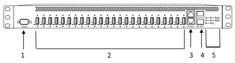
AnywhereUSB 24 Plus: Front panel
| Item | Name | Description | |
|---|---|---|---|
| 1 | DB9 Console | Used to access a console using the RS232 DTE interface. | |
| 2 |
USB ports and LEDs |
Group of 24 USB ports and LEDS. The USB port supports 1.1, 2.0, and 3.1 USB devices. The LED illuminates as follows:
Note When connecting a USB cable to a USB port on the Hub, make sure to use a high-quality USB standards-compliant cable. |
|
| 3 | ETH 1/2 |
Connect a Cat 7 STP Ethernet cable. ETH1 is the primary network interface. See Step 5: Connect to the Hub using an Ethernet LAN connection. ETH2 is the secondary network interface. This is optional and used for redundancy. Note Digi recommends that you use either the Ethernet cable or the SFP+ module. If both the Ethernet cable and the SFP+ module are connected, data is sent and received by SFP+ only. Ethernet is not used to send or receive data. |
|
| 4 | SFP+ 1/2 |
Connect an SFP transceiver module for fiber connection, such as Finisar Network FTLX8574D3BCL SFP+. The second SFP+ module is optional and used for redundancy. Note Digi recommends that you use either the Ethernet cable or the SFP+ module. If both the Ethernet cable and the SFP+ module are connected, data is sent and received by SFP+ only. Ethernet is not used to send or receive data. |
|
| 5 |
Fan1 LED |
The LED shows the status of Fan 1: |
|

|
Solid green The fan is running within normal range of use. |
||

|
Solid red The fan slows down or the Hub is overheating. |
||
| 5 |
Fan2 LED |
The LED shows the status of Fan 2: |
|
|
|
Solid green The fan is running within normal range of use. |
||
|
|
Solid red The fan slows down or the Hub is overheating. |
||
| 5 |
User LED |
LED used for the Find Me feature. When this feature is activated, the LED blinks orange and then green. |
|
| 5 |
PSU1 LED |
The LED shows the status of PSU1 (Power Supply Unit 1). The status of PSU1 (on or off) can also be viewed on the web UI dashboard in the Device section. A change in PSU status is included as a system event in the system event log. |
|
|
|

|
Solid blue The Hub is powered on. |
|

|
Solid red The Hub is not powered or the supply has failed. |
||
| 5 |
PSU2 LED |
The LED shows the status of PSU2 (Power Supply Unit 2). The status of PSU2 (on or off) can also be viewed on the web UI dashboard in the Device section. A change in PSU status is included as a system event in the system event log. |
|
|
|
Solid blue The Hub is powered on. |
||
|
|
Solid red The Hub is not powered or the supply has failed. |
||
| 5 |
Wi-Fi Service LED |
Reserved for future use. | |
| 5 |
WWAN1 Signal LED
WWAN2 Service LED |
The WWAN1 Signal and WWAN2 Service LEDs how the status of the WWAN connection while actions are being taken by the modem firmware. After all actions are completed, the WWAN Signal LED shows modem strength and the WWAN Service LED shows additional information. See WWAN LED description table below for more information. |
|
WWAN Service and WWAN Signal LED descriptions
| WWAN Signal LED | WWAN Service LED | Description | |
|---|---|---|---|
| Slow flash red | Slow flash red | Updating modem firmware | |
| Slow flash green | Slow flash green | Recovering modem firmware | |
| Off | Slow flash green | Waiting for modem to appear | |
| Off | Off | Modem not present. | |
| Off | Solid green | Modem is connected | |
| Off | Solid red | No SIM card present | |
| Off | Fast flash green | Connecting | |
| Solid green | Off | Modem signal strength: 5 bars | |
| Fast flash green | Off | Modem signal strength: 3-4 bars | |
| Slow flash green | Off | Modem signal strength: 1-2 bars | |
| Slow flash red | Off | Modem signal strength: 0 bars | |
| Off | Off | Modem signal strength: * | |
 PDF
PDF


