This section applies to Digi products equipped with EIA-422 asynchronous
interfaces.
Physical Cable Characteristics
EIA-422 interface cables should be shielded twisted-pair cables. Each
signal requires two leads (one twisted pair of wires) to complete a balanced
voltage digital circuit. The shield should be connected to the Chassis
Ground of the devices at both ends of the interface cable.
Interface Signaling
The EIA-422 interface provides four signals: Transmitted Data (TxD),
Received Data (RxD), Request To Send (RTS) and Clear To Send (CTS).
The functions of these signals are identical to their EIA-232 counterparts.
Grounding Requirements
EIA-422 interface cables must provide a ground path between the devices
to be connected. This ensures the integrity of data transfers and control
signals. This should be connected to the Chassis Ground of each device.
Digi recommends using the cable shield for this purpose.
Digi EIA-422 Connector Wiring
A terminal, a serial printer, or a serial port for another computer usually
functions as a DTE device. The Digi adapter is also a DTE device. To
connect a DTE device to another DTE device a null modem cable or
adapter must be used.
Two wires (one twisted pair) are required for each signal, a positive lead
("+"), and a negative lead ("-"). The "+" leads at one end of the cable must
be connected to the "+" leads at the other end, and the "-" leads at one end
must be connected to the "-" leads at the other end.
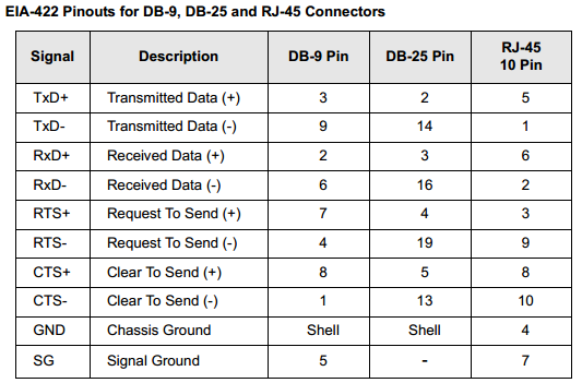
Incorrect wiring could result in damage to the connected devices. The
following table shows the pin configurations for the EIA-422 versions of
Digi DB-9, DB-25, and RJ-45 connectors:

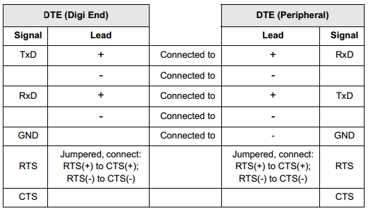
EIA-422 Software Handshaking (XON/XOFF) Cable
Use the chart below as a guide for EIA-422 wiring:

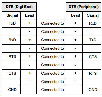
EIA-422 Hardware Handshaking (Ready/Busy) Cable
Use the following table as a guide for EIA-422 wiring.

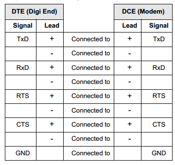
EIA-422 DTE to DCE (Modem) Cable
Use the chart below as a guide for EIA-422 modem wiring:

Last updated:
Jan 01, 2024