Would you like an LED bar graph to wirelessly show you how bright or dim a room is elsewhere? Well this is just the solution for you! This project uses an MBed microcontroller, light sensor, LED bar graph, and a pair of XBee radios to get you going on monitoring brightness without even being there.
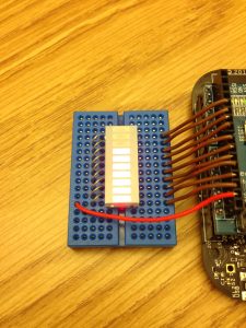 Standard Lighting
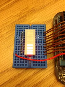 Dim Lighting
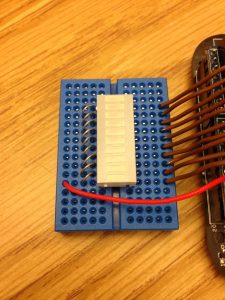 Dark
Parts:
- One solderless breadboards (MS MKKN2, AF 64, DK 438-1045-ND, SFE PRT-09567)
- Hookup wire or jumper wire kit (MS MKSEEED3, AF 153, DK 923351-ND, SFE PRT-00124)
- XBee USB serial adapter (XBee Explorer or Digi Evaluation board) (AF 247, SFE WRL-08687)
- One XBee shield (Seeed Studio SLD01103P, Arduino A000065, SF WRL-10854)
- Wire strippers (AF 147, DK PAL70057-ND, SFE TOL-08696)
- One 20K ohm resistor (DK P20KBACT-ND)
- One mini-breadboard (DK 923273-ND, SPE PRT-12046)
- One 10 Segment LED Bar Graph (DK ELB-1010SURD, SFE COM-09935)
- One AA battery holder with connection wires (RS 270-408, SFE PRT-09547)
- Two AA batteries
- One 10K ohm photoresistor (also called an LDR or light-dependent resistor) (AF 161, DK PDV-P8001-ND, SFE SEN-09088)
- One XBee radio (Series 2/ZB firmware) configured as a Zigbee Coordinator API mode (Digi: XB24-Z7WIT-004, DK 602-1098-ND)
- One XBee radio (Series 2/ZB firmware) configured as a Zigbee Router AT mode (Digi: XB24-Z7WIT-004, DK 602-1098-ND)
- One XBee breakout board with male headers and 2 mm female headers installed (AF 126 [add SFE PRT-00116], SFE BOB-08276, PRT-08272, and PRT-00116)
- USB cable for XBee adapter (AF 260, SFE CAB-00598)
- One Mbed Freedom board (Freescale FRDM-KL25Z)
- Soldering tools (any hardware store)
- A determined mind
Using the Mbed Online Compiler
This project used the Mbed software, known as the online compiler, in order to program the Mbed microcontroller. You can sign up for a free account to access the online compiler at
www.mbed.org. There are many versions of the Mbed, so make sure you select the correct platform. A basic guide to how to use it can be found at the same Mbed website.
Prepare and Configure your Coordinator Radio
- Use X-CTU to set the designated coordinator radio in API mode.
- Configure the coordinator radio with a PAN ID (between 0x0 and 0xFFFFFFFFFFFFFFFF). Make sure you note this ID so that you can set up your router radio with the same one.
- Enter in the High and Low destination addresses of your router radio.
- Set the sampling rate to 0x64 (100 samples per second).
Prepare and Configure your Router Radio
- Use X-CTU to set the designated router radio in AT mode.
- Configure the router radio with the PAN ID you set the coordinator radio with.
- Set JV to 1 to ensure that your router attempts to rejoin the coordinator on startup.
- Enter in the High and Low destination addresses of your coordinator radio.
- Set pin 0 to mode 2, which is analog mode.
Construct the Bar Graph-XBee Connection
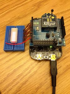
Figure 1
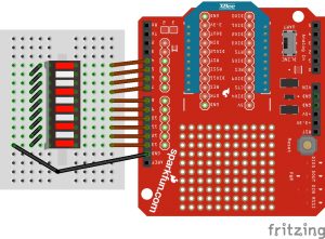
Figure 2.
- Attach your XBee coordinator radio to the XBee shield, and then attach it to the MBed board.
- Attach the 10 LED Bar Graph to the center of the small breadboard.
- Use metal pins from resistors and connect the left side (ground side) of the bar graph pins together to create a common ground. There are many ways of doing this, so use Figures 1 and 2 for reference.
- Connect a wire from pin 1 to Mbed pin PTD1 (shield pin 13).
- Connect a wire from pin 2 to Mbed pin PTD3 (shield pin 12).
- Connect a wire from pin 3 to Mbed pin PTD2 (shield pin 11).
- Connect a wire from pin 4 to Mbed pin PTD0 (shield pin 10).
- Connect a wire from pin 5 to Mbed pin PTD5 (shield pin 9).
- Connect a wire from pin 6 to Mbed pin PTA13 (shield pin 8).
- Connect a wire from pin 7 to Mbed pin PTC9 (shield pin 7).
- Connect a wire from pin 8 to Mbed pin PTC8 (shield pin 6).
- Connect a wire from pin 9 to Mbed pin PTA5 (shield pin 5).
- Connect a wire from pin 10 to Mbed pin PTA4 (shield pin 4).
- Connect a wire from the free MBed ground pin closest to the breadboard to any ground pin on the LED (pin 1 is recommended for easiest access).
Program the MBed microcontroller
Upload the following program to the main.cpp of the Mbed microcontrollers. Be sure to include mbed.h, which can be found online.
#include "mbed.h"
Serial xbee(USBTX, USBRX);
DigitalOut one(PTD1);
DigitalOut two(PTD3);
DigitalOut three(PTD2);
DigitalOut four(PTD0);
DigitalOut five(PTD5);
DigitalOut six(PTA13);
DigitalOut seven(PTC9);
DigitalOut eight(PTC8);
DigitalOut nine(PTA5);
DigitalOut ten(PTA4);
int analogValue = 0;
int main() {
while(1) {
if (xbee.readable() >= 21) {
if (xbee.getc() == 0x7E) {
for (int i = 0; i < 18; i++) {
int discard = xbee.getc();
}
int analogHigh = xbee.getc();
int analogLow = xbee.getc();
analogValue = analogLow + (analogHigh * 256);
}
}
if (analogValue <= 100) {
one = 1;
two = 1;
three = 1;
four = 1;
five = 1;
six = 1;
seven = 1;
eight = 1;
nine = 1;
ten = 1;
}
if (analogValue > 100 && analogValue <= 200) {
one = 1;
two = 1;
three = 1;
four = 1;
five = 1;
six = 1;
seven = 1;
eight = 1;
nine = 1;
ten = 0;
}
if (analogValue > 200 && analogValue <= 300) {
one = 1;
two = 1;
three = 1;
four = 1;
five = 1;
six = 1;
seven = 1;
eight = 1;
nine = 0;
ten = 0;
}
if (analogValue > 300 && analogValue <= 400) {
one = 1;
two = 1;
three = 1;
four = 1;
five = 1;
six = 1;
seven = 1;
eight = 0;
nine = 0;
ten = 0;
}
if (analogValue > 400 && analogValue <= 500) {
one = 1;
two = 1;
three = 1;
four = 1;
five = 1;
six = 1;
seven = 0;
eight = 0;
nine = 0;
ten = 0;
}
if (analogValue > 500 && analogValue <= 600) {
one = 1;
two = 1;
three = 1;
four = 1;
five = 1;
six = 0;
seven = 0;
eight = 0;
nine = 0;
ten = 0;
}
if (analogValue > 600 && analogValue <= 700) {
one = 1;
two = 1;
three = 1;
four = 1;
five = 0;
six = 0;
seven = 0;
eight = 0;
nine = 0;
ten = 0;
}
if (analogValue > 700 && analogValue <= 800) {
one = 1;
two = 1;
three = 1;
four = 0;
five = 0;
six = 0;
seven = 0;
eight = 0;
nine = 0;
ten = 0;
}
if (analogValue > 800 && analogValue <= 900) {
one = 1;
two = 1;
three = 0;
four = 0;
five = 0;
six = 0;
seven = 0;
eight = 0;
nine = 0;
ten = 0;
}
if (analogValue > 900 && analogValue <= 1000) {
one = 1;
two = 0;
three = 0;
four = 0;
five = 0;
six = 0;
seven = 0;
eight = 0;
nine = 0;
ten = 0;
}
if (analogValue > 1000) {
one = 0;
two = 0;
three = 0;
four = 0;
five = 0;
six = 0;
seven = 0;
eight = 0;
nine = 0;
ten = 0;
}
}
}
Construct the Light Photoresistor-XBee connection
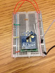
Figure 3.

Figure 4.
- Hook up the positive battery lead to one of the power rails on the breadboard.
- Hook up the ground battery lead to a ground rail on the breadboard.
- Hook up power and ground across the breadboard so that the rails on both sides are live.
- With the router XBee mounted on the breakout board, position the breakout board in the center bottom of the breadboard so that the two rows of male header pins are inserted on opposite sides of the center trough.
- Use red hookup wire to connect pin 1 (VCC) of the XBee to 3-volt battery power.
- Use black hookup wire to connect pin 10 (GND) of the XBee to ground.
- Attach a photoresistor between ground and XBee digital input 0 (physical pin 20).
- Make sure you use the 20K ohm (or other value that’s double your photo resistor’s max value) pull-up resistor from digital input 0 to power. This ensures the sensor has a proper voltage divider circuit, which is required to get correct readings.
- Refer to Figures 3 and 4 for visual reference.