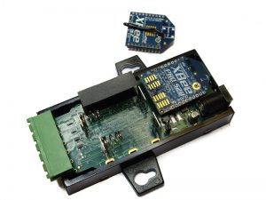
In this post, we are going to change the XBee module included in the XBee Digital I/O Adapter (DIO) for a Programmable XBee, then install the example Programmable DIO code.
If you have Digi's Programmable XBee SDK, you'll already have an example of how this set up works.
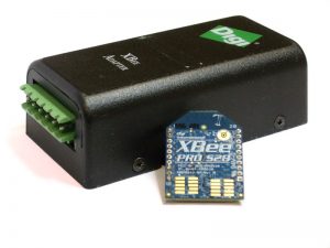
Here we have a DIO with the original XBee:
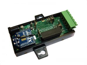
Here's the DIO with the programmable XBee:
This example increases the capacities of the DIO, with features like:
- Digital Inputs
- Open-Collector outputs
- Pulse counters
- Double contact pulse counters
- Pulse-Width Modulated output
- Simple frames operation
To test the Programmable DIO you need to install CodeWarrior 10.2 (download it from Digi here) and Programmable XBee SDK (download it from Digi here).
Once installed, open CodeWarrior, go to File -> New -> Programmable XBee Sample Project. In the new window that pops up, select the sample “Programmable DIO Example” found under the “Applications -> Zigbee” item.
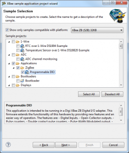
Now, you should build and flash the "Programmable DIO Example" demo application into the Programmable XBee.
Hardware settings:
You will need one X-Stick or XBee gateway running as a coordinator to send the AT frames (see readMe.txt in the example for more information).
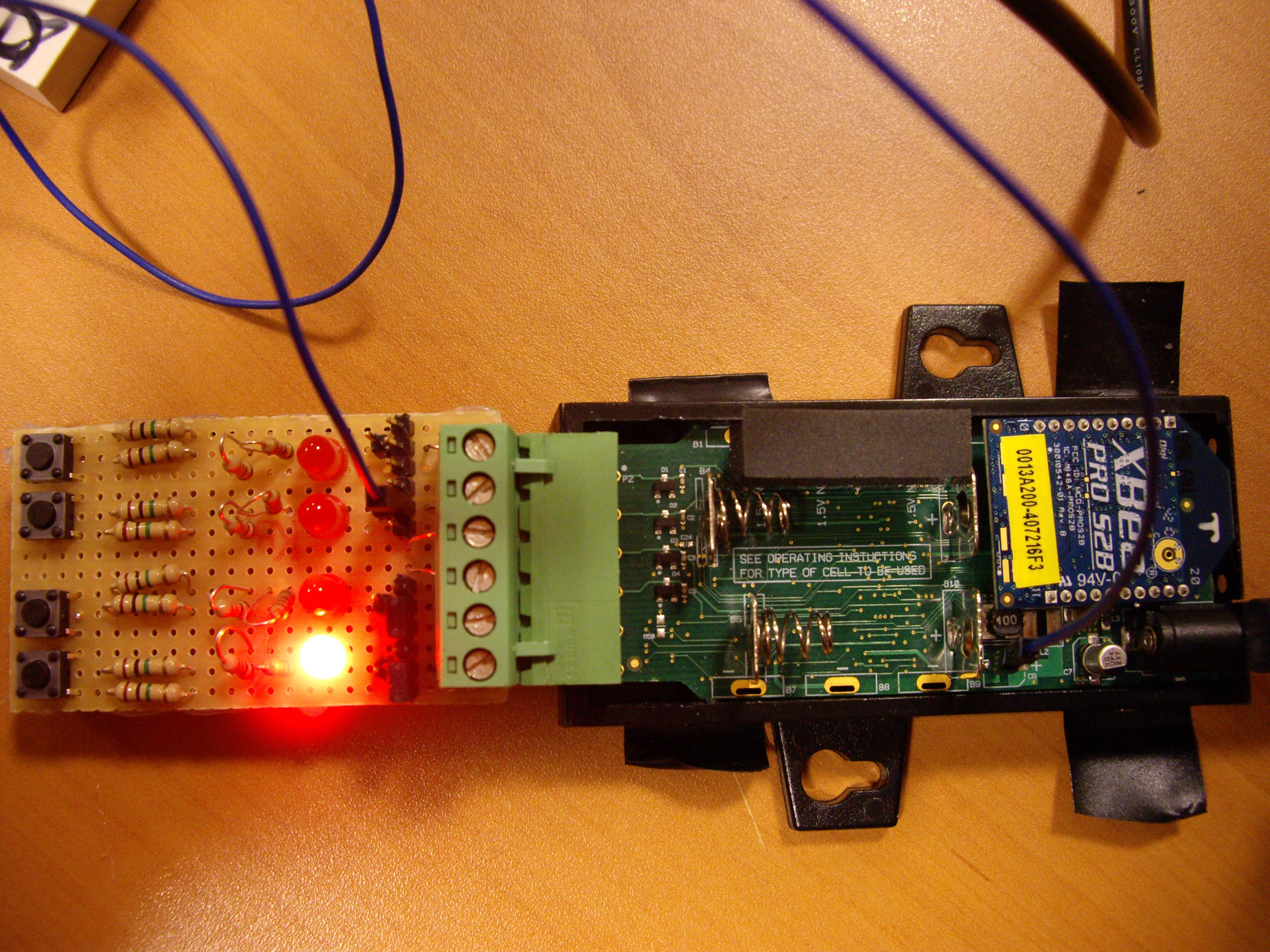
You will also need a board to see the inputs and the outputs, here's a schematic of this board:
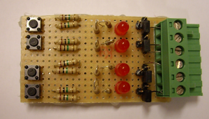
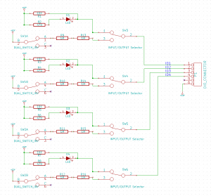
Then, you will send a frame with XCTU, to configure the IO4 like OUTPUT, and another to set the output to 0 (outputs are inverted).
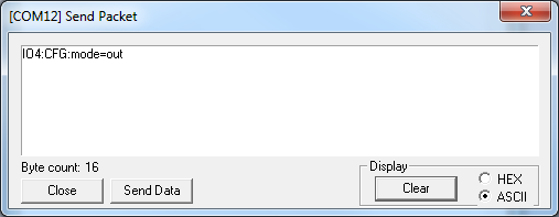
Configure the IO4 like output
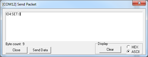
Set 0 to the output
And, finally, here's the result:
Enjoy!