What's involved in calculating free space path loss, and when do you need it? Free space path loss (FSPL) is the reduction in signal strength that occurs when an electromagnetic wave travels through free space, such as air or a vacuum, without any obstacles to interfere with it. It's a key concept in radio frequency engineering and wireless communications. This calculation can help you to identify signal strength. This is useful, for example, when planning a deployment of cellular routers, such as Digi's enterprise, industrial or transportation solutions.
FSPL calculations are theoretical and are a good approximation for estimating signal loss in free space. For real-world applications, it is important to take a range of factors into account, such as concrete buildings and other obstacles, in order to assess signal strength at the given location. Therefore, the calculations can be tricky, given that you need to account for those obstacles and other considerations. And even though there are online calculators, such as on the EverythingRF site, they may not account for those challenges either. The good news is that if you don't have the staff to go out and perform site surveys or calculate signal strength prior to your deployment, Digi Professional Services can help.
How to Calculate FSPL
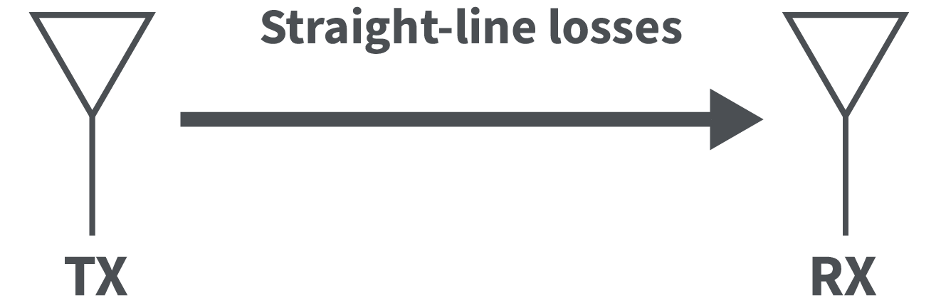
The overall point-to-point loss a signal will encounter when traveling unhindered between the transmitting and receiving antennas is known as the free space route loss. The loss that occurs when traveling in a straight line between the transmitting and receiving antennas is known as the free space route loss.
In terms of the distance (d) and transmitting frequency (f), the free space path loss is defined below:
 Next, using the free space path loss, the expected power to be observed at the receiver can be calculated. The receiver in this case is located after the antenna, any cables or connectors, transmission lines on the PCB, filters and any other components like impedance matching network. The expected receiver power is defined as:

In this equation, there are several terms that are defined below:
In another approach, the designer specifies the transmitter power with the receiver sensitivity and the maximum propagation distance is determined for a given frequency. The distance is calculated using the free space path loss formula shown above. To so this, we solve for FSPL in the receiver power equation, plug this into the FSPL formula and solve for the distance to get the following result:
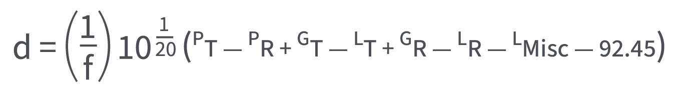 Here again, we have the frequency (f) in GHz and the distance (d) in Km. The distance here is also a straight-line distance not accounting for any multipath effects or other obstacles that could create additional losses.
Next Steps
Reference: RF Link Budget Calculation Guide, by Cadence System Analysis