Modbus Example Serial Adapter
Modbus Bridge Example - Xbee-Serial Adapters
This is the serial node portion of an Modbus Bridge example using a Digi ConnectPort X4 as the central Modbus/TCP bridge and a collection of serial and Ethernet nodes.
To see how to Bridge mesh to Modbus/TCP server/slaves, see this web page: Modbus Example Ethernet Adapter.
Supported Models
Any of the Digi serial adapters can be used as part of your Modbus bridge, including:
- Digi XBee RS-232 adapter (Xbee to RS-232 with DB9 DTE/Male port)
- Digi XBee RS-485 Adapter (XBee to RS-422, RS-485 4-wire and RS-485 2-wire with screw terminals)
- Digi XBee RS-232 PH Adapter (Self-Powered Xbee to RS-232 with DB9 DCE/Female port)
Product Installation
Confirm that you have the correct power for your model - probably 3-6vdc (yes, sadly support for 12vdc and 24vdc was discontinued)
Confirm that your adapter has a appropriate level of XBee firmware. If you obtained the XBee adapter at the same time as the X4 gateway, then this should be true.
XBee 232 Adapter Installation
The RS-232 port is like a standard PC or computer port, so the same cables used with a PC should work.
See Digi XBee RS-232 adapter for more information.
XBee 485 Adapter Installation
Select the use of RS-422/RS-485 4-wire or RS-485 2-wire via the DIP Switches, and connect your wires. Pay special attention to the signal ground, for even if the end-device claims pure 4 or 2-wire use without ground, the Digi supplied AC/DC supplies have a floating earth and will not communicate reliably without the correct reference-ground connection.
See Digi XBee RS-485 Adapter for more information.
Detailed Serial Settings
Although summarized information is given below, more detailed information is given on this page Setting Serial Adapter Baud Rate.
Confirm the XBee adapter is Associated
Covering the entire concept of ZigBee and association is beyond the scope of this Modbus Serial Example, however the XBee serial adapter should show the rapid LED blink of association, plus it should be included on the Network View of the XBee Devices on your Digi ConnectPort gateway.
If your system is the only ZigBee network within RF range, this should happen fairly trivially. Just remember that your neighbors might have ZigBee systems, so your XBee adapters might even associate to a ZigBee coordinator in another building.
If you are surrounded by active ZigBee networks, then very likely your XBee adapter will associate with the wrong system. For example, I have from 2 to 6 distinct ZigBee gateways active at any one time, so I am forced to repeatedly press the commissioning push-button 4 times until the adapter associates with the correct Digi ConnectPort. See the Chapter 'Network Commissioning and Diagnostics' in your XBee Module manual for more details.
XBee Module Configuration
If your serial adapter is properly associated, it will be show within the Digi ConnectPort's Network View of the XBee Devices, plus the 16-bit network Address will not be [fffe].
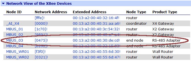
In this example, we'll be working on the node named MBUS_03, so click the blue link-enabled Extended (or MAC) Address to pull up the XBee information for this device. If the device is sleeping or no longer associated, then you will not see the dialog show below, but instead will see a warning that "Settings are not configurable for this device." This does not truly mean that the setting are not configurable, but that an attempt to fetch such settings failed.
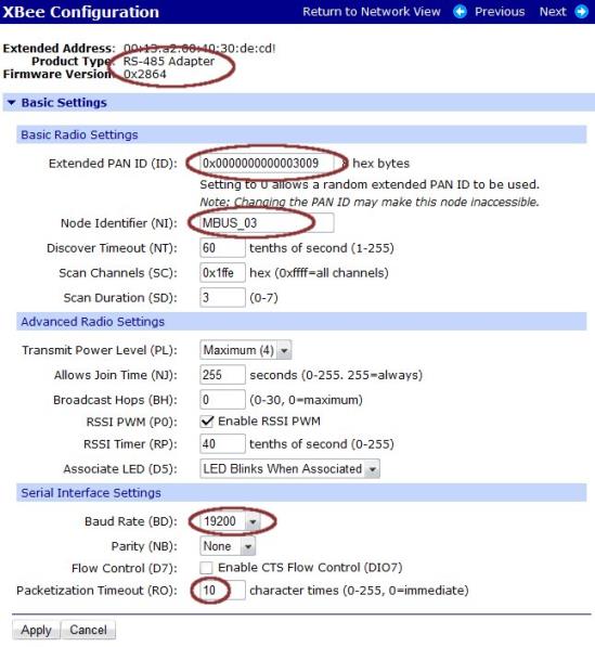
On the XBee Configuration - Basic Settings page:
- Confirm the Extended Address, Product Type and Firmware are appropriate.
- Manually force the Extended PAN ID to be your fixed value. As long as this value is zero (0x0000000000000000), then your adapter may associate with any ZigBee coordinator within RF range. True, it will "prefer" to remain associated to the current X4, yet someday it will move. So always hard-code your desired PAN ID. A phone number is a good, memorable PAN ID.
- Add a user-friendly Node Identifier - by default this will be a single SPACE character. If you are doing low-level API message formatting, then you can query device addresses based on this name, however for most users it only makes the gateway XBee display more useful.
- Set the correct Baud Rate and parity. (Sorry, at the moment the Digi Xbee modules do not support 7 data bits, so it is not possible to support Modbus/ASCII at 7,E,2)
- The default Packetization Timeout of 3 characters is fine per the Modbus serial standard, however I tend to relax it to 10 (or 25) character times since the added few msec of delay is less significant at an application level than prematurely fragmented response packets.
Remember to press the APPLY button to send the settings down the to XBee Adapter!
(Late Breaking info - screen shot to be added) : If you are using the Digi XBee RS-485 Adapter and configuring it through the web UI, uncheck the CTS flow control check-box (turn it off) on the Basic Settings page, then go to the Advanced Settings page and put a seven (7) into the DIO7 configuration (D7): setting.
If your adapter is set to sleep, pressing the commissioning push-button once (the Node Identification function) will wake the adapter for 30 seconds, which is enough time to READ these settings. Before trying to APPLY or save any changes, press the commissioning push-button again to gain another 30-seconds of wake time.
IA Engine Configuration
At this point your XBee serial adapter should be properly associated, with the correct basic settings forced down and saved to the adapter.
Now add the Modbus Message Destination (or IA route) to the Digi ConnectPort gateway Modbus configuration. See this page if you require step-by-step instructions on adding the IA Message Destination: Modbus bridge on CPX4.
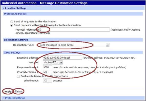
The relevant information on this page are:
- Most likely you only want a subset of Modbus messages to go to this XBee serial adapter. So click the radio button to enable only forwarding selected requests to this destination.
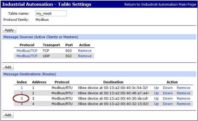
- If there is a single Modbus device on this XBee adapter, then just enter the correct Modbus serial slave address (the value 3 is shown in the example above).
- If there are more than 1 Modbus device on this XBee adapter, then enter the Modbus serial slave address as either a range (such as "10-15") or as a scattered list (such as "7,10,15,16")
- Note that there is NO relationship between the table index (in this example 3) and the Protocol Addresses (which in this example is also 3). The index only defines the order in which the Modbus IA Engine scans to locate the correct destination to answer the Modbus request.
- If you need to adjust/change the slave address - see below.
- Destination Type must be Send messages to XBee device.
- The Extended address must be manually entered as required - there is no automatic way to have this information entered, but you can carefully open a Network View in another browser tab and carefully do a cut-and-paste of the address show. If you change the Xbee endpoint, then add the new endpoint after the '!', so if the endpoint is changed away from 0xe8 to 0xe9 to avoid port-bind conflict with Python or iDigi/Dia, then in this example enter the MAC as 00:13:a2:00:40:30:de:cd!E9.
- Select the appropriate Protocol of Modbus/RTU or Modbus/ASCII. Remember that 7,E,2 cannot be supported with Modbus/ASCII - please complain to Digi sales if you find this as annoying as I do. The Xbee hardware supports it, but Product Management does not believe anyone wants to use such settings.
- The Response timeout must be at least 5000 msec (5 seconds) because the ZigBee mesh at times does route discover and other housekeeping which will cause responses to be returned in about 5 seconds. If you cannot tolerate 5 seconds timeouts, then do not use ZigBee - or do not use Modbus/RTU. Unfortunately, Modbus serial offers no support for detecting stale responses. So setting the Response timeout to 1 second might result in automation system misoperation as stale (old) data is misapplied to the wrong registers.
- The Character timeout should be 500 msec or larger. Again, ZigBee is not a high-performance Modbus transport; the nature of the multi-path, fault-tolerant mesh means transactions take a variable amount of time to complete.
Remember to press the APPLY button to save the settings within the gateway.
To enter a NEW message destination, press the RETURN button to return to previous menu. Editing the values on the current page and pressing APPLY a second time merely CHANGES the values in this current destination - it does not create a new route.
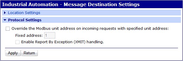
Handling Modbus slave address issues
Suppose you have 10 Modbus/RTU serial devices and they all have the slave address one (1). Can you still use a Digi ConnectPort to bridge to them without forcing a change in the end device?
Yes, you can. From the network standpoint they will all need to have unique Modbus unit id or slave addresses, however the Digi Modbus IA Engine can map or fix-up the address on the outgoing requests. So as example you might chose to call the 10 devices slave address 50 to 59.
Clicking on the Protocol Settings section of the Message Destination. You will see the dialog below. By enabling the "Override the Modbus unit address ..." option, you can enter the Fixed Address 1 on every route. This causes the route for slave address 50 to swap in the value 1 over the XBee mesh, and to restore the address 50 in the responses.
Summary
This completes your addition of an Xbee serial adapter for use with Modbus serial. The Digi ConnectPort gateway IA Table Settings summary will look like this. Click on the index number to re-open the settings page for this destination. Remember that the IA engine scans this list from top to bottom, sending the message to the first destination with a matching Modbus protocol address. So if you enter the address a the range 0-255 in the first route of 4, none of the other 3 will ever be used.
 PDF
PDF


