Modbus Example Ethernet Adapter
Modbus Bridge Example - Ethernet Adapters
This is the XBee to Ethernet node portion of an Modbus Bridge example using a Digi ConnectPort X4 as the central Modbus/TCP bridge and a collection of serial and Ethernet nodes.
This page shows how to enable XBee wireless to be bridged to Modbus/TCP servers (or slaves). This is not directly related to use of Modbus/TCP to query remote nodes via XBee wireless.
To see how to Bridge mesh to Modbus/RTU serial slaves, see this web page: Modbus Example Serial Adapter.
Supported Models
Digi ConnectPort X2 when loaded with firmware 82001596 (Ethernet model) or 82001630 (Wi-Fi model), which supports Python.
Product Installation
Confirm that you have the correct power for your ConnectPort X2 - probably 9 to 30vdc. If you want to use an existing shared 12vdc or 24vdc supply, Digi sells a power-pigtail with the correct locking barrel connector - details are here: Locking Power Connecter.
You'll also need to make sure the appropriate antenna is installed - and if the CP-X2 is to be installed inside of a metal enclosure, you'll need to plan to mount the appropriate external antenna options.
Reflash the CPX2's XBee Module
To allow Modbus/RTU traffic on the XBee wireless to bridge to local Ethernet servers, you'll need the XBee module to be flashed with the XBee Router API firmware (such as 0x2364) - not the default XBee Coordinator API firmware. Quite literally, you need the CPX2 to be a member of the central CPX4 bridge's mesh, so the CPX4's XBee is to be the Coordinator; not the CPX2's XBee.
You can either:
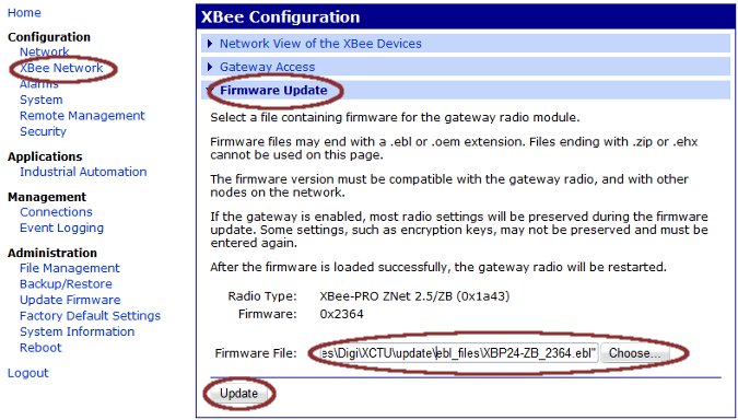
Use the web UI to upload the EBL file (such as XB24-ZB_2364.ebl or XBP24-ZB_2364.ebl)
If you instead dissemble the CPX2 unit and manually reflash the XBee using a serial or USB development board, then make sure you enter the settings below. These should already be handled if you used the web UI:
- Load Destination Address High (DH) with the upper 4 bytes of your CPX4 gateway XBee address
- Load Destination Address Low (DL) with the lower 4 bytes of your CPX4 gateway XBee address
- Set the lower 16-bits of the Device Type Identifier to 0x0003 to define this as a CPX2
As a second step, enter this Setting:
Set the Baud Rate to 115200 (BD=7). This will have defaulted back to 9600 after you reflashed the XBee firmware, plus XCTU might give you an error as you try to set this.
Configure the CPX2's XBee Module
If the CPX2 and XBee are properly configured, then the CPX2 will show up on both the "Network View" of the Digi ConnectPort X4 (the central bridge) and on that of the Digi ConnectPort X2. You can configure the following settings via either the CPX4 or the CPX2:
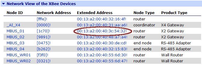
Click on the appropriate Extended Address (MAC address) link and you will see the Basic settings page:
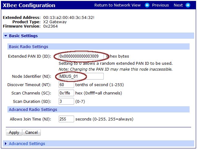
On the XBee Configuration - Basic Settings page:
- Confirm the Extended Address, Product Type and Firmware are appropriate.
- Manually force the Extended PAN ID to be your fixed value. As long as this value is zero (0x0000000000000000), then your CPX2 may associate with any ZigBee coordinator within RF range. True, it will "prefer" to remain associated to the current CPX4, yet someday it will move. So always hard-code your desired PAN ID. A phone number is a good, memorable PAN ID.
- Add a user-friendly Node Identifier - by default this will be a single SPACE character. If you are doing low-level API message formatting, then you can query device addresses based on this name, however for most users it only makes the gateway XBee display more useful.
Enabling the Python application to do the bridging
To enable the bridging of XBee wireless packets to local Modbus/TCP server/slaves, you'll need to upload the appropriate Python files to your CPX2.
Create the address.txt file
The first generation of this tool supports a single Modbus/TCP server/slave, and its IP address must be uploaded in the text file named "address.txt". The ":502" at the end is optional, but can be used to change the default TCP port number to use.
192.168.196.6:502
Uploading the Files
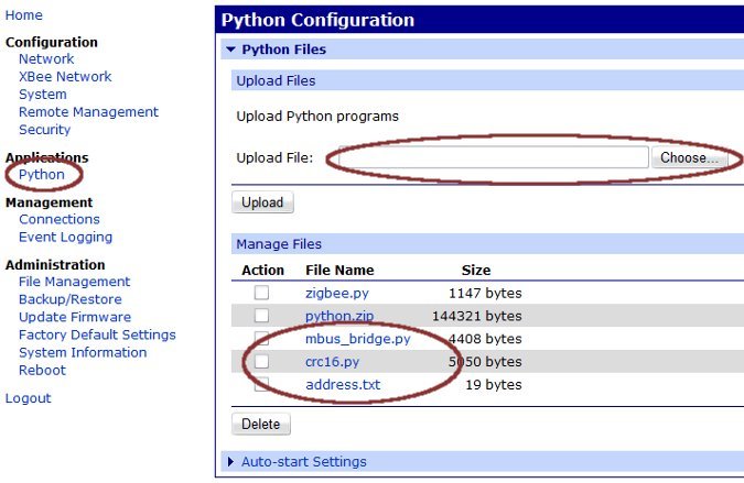
Click the Python Application link, then upload the three files: mbus_bridge.py, crc16.py and address.txt. They are contained in this ZIP file: X2_mbus_2009Sep13.zip.
The file list should look similar to that below, however the file sizes may vary:
Enable auto-start of the bridging
After uploading the files, click the Auto-Start Settings section and enter the mbus_bridge.py.
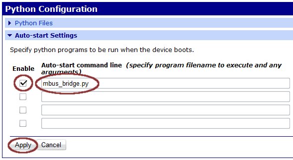
Note that this Python application closes all sockets and sleeps for 60 seconds anytime there is a fault. So if you are moving Ethernet cables around or doing other disruptive things, the CPX2 might not appear to function for a minute or two.
 PDF
PDF


