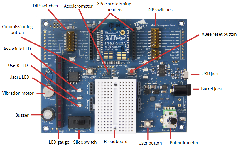
Development board components
This section contains information about the components on the development board.

The table below contains an alphabetized list of the components on the board.
| Item | Description | |||||||||||||||||||||||||||
|---|---|---|---|---|---|---|---|---|---|---|---|---|---|---|---|---|---|---|---|---|---|---|---|---|---|---|---|---|
| Accelerometer | The accelerometer drives the Tilt widget. You can control the accelerometer through the XBee Zigbee dashboard. | |||||||||||||||||||||||||||
| Associate LED |
The Associate pin (pin 15) provides an indication of the device's sleep status and diagnostic information.
To enable the associate LED functionality, set the D5 command to 1; it is enabled by default. If enabled, the Associate pin is configured as an output. This section describes how the pin behaves.
The Associate pin indicates the synchronization status of a sleep compatible XBee Gateway. If a device is not sleep compatible, the pin functions as a power indicator.
Use the LT command to override the blink rate of the Associate pin. If you set LT to 0, the device uses the default blink time: 500 ms for a sleep coordinator, 250 ms otherwise.
The following table describes the Associate LED functionality.
|
|||||||||||||||||||||||||||
| Barrel jack |
Accepts 4.5 V to 24 V. You can use the barrel jack with the battery pack provided with the kit. |
|||||||||||||||||||||||||||
| Breadboard | ||||||||||||||||||||||||||||
| Buzzer | You can use the buzzer as an alarm to indicate trouble. You can control the buzzer through the XBee Zigbee dashboard. Use the buzzer toggle widget to turn the buzzer on/off. | |||||||||||||||||||||||||||
| Commissioning button |
The XBee Zigbee development board supports a set of commissioning and LED functions to help you deploy and commission devices. These functions include the Commissioning button definitions and the associated LED functions.
Definitions To enable the Commissioning button functionality on pin 20, set the D0 command to 1. The functionality is enabled by default.
You must perform multiple button presses within two seconds.
The following table provides the button definitions.
Use the Commissioning button Use the CB command to simulate button presses in software. Send CB with a parameter set to the number of button presses to perform. For example, if you send ATCB1, the device performs the action(s) associated with a single button press.
The Node Identification Indicator (0x95) frame is similar to the Remote Command Response (0x97) frame—it contains the device’s address, node identifier string (NI command), and other relevant data. All devices in API operating mode that receive the Node Identification Indicator frame send it out their UART as a Node Identification Indicator frame.
If you enable the Commissioning button during sleep, it increases the sleeping current draw, especially in Asynchronous pin sleep (SM = 1) mode. When asleep, hold down the Commissioning button for up to two seconds to wake the device from sleep, then issue the two or four button presses. |
|||||||||||||||||||||||||||
| Diagnostics support | The Associate pin works with the Commissioning button to provide additional diagnostic behaviors to aid in deploying and testing a network. If you press the Commissioning button once, XBee Gateway transmits a broadcast Node Identification Indicator (0x95) frame at the beginning of the next wake cycle if the device is sleep compatible, or immediately if the device is not sleep compatible. If you enable the Associate LED functionality using the D5 command, a device that receives this transmission blinks its Associate pin rapidly for one second. | |||||||||||||||||||||||||||
|
DIP switches (back or underside of board) |
Set the board for use with XBee Zigbee or XBee Wi-Fi modules. For more information, see XBee Zigbee/Wi-Fi DIP switches on the XBee development board. | |||||||||||||||||||||||||||
|
DIP switches (top of board) |
Allows components on the development board to be disconnected from the XBee Zigbee module. If the switch is away from the XBee Zigbee module, the XBee pin is connected to that built-in widget on the XBee Zigbee dashboard. If the switch is towards the XBee, the XBee pin is disconnected from that component. Note When you use loose components or do advanced prototyping, you may need to disconnect the built-in component from the XBee pin. |
|||||||||||||||||||||||||||
| LED gauge | Controlled through the XBee Zigbee dashboard, the LED gauge can be toggled on or off. | |||||||||||||||||||||||||||
| Potentiometer | You can choose to report the data from the potentiometer to the XBee Zigbee dashboard as a speedometer gauge, progress bar, or a graph. You can control the potentiometer by turning the adjustable knob left or right. | |||||||||||||||||||||||||||
| Push button | The state of the push button appears on the XBee Zigbee dashboard. The push button only displays ON when you are actively pushing the button. | |||||||||||||||||||||||||||
| Slide switch | The state of the slide switch is indicated on the XBee Zigbee dashboard. Similar to a light switch, it stays either on or off. | |||||||||||||||||||||||||||
| USB jack | You can use the USB jack to power the development board. The USB jack also provides serial port access to the XBee Zigbee for configuration or sending and receiving data to and from Remote Manager. | |||||||||||||||||||||||||||
| User0/TCP LED |
You can control the User0/TCP LED through the XBee Zigbee dashboard. |
|||||||||||||||||||||||||||
| User1/On LED |
You can control the User1/On LED through the XBee Zigbee dashboard. |
|||||||||||||||||||||||||||
| Vibration motor |
The vibration motor indicates a change in status. You can control the vibration motor through the XBee Zigbee dashboard. |
|||||||||||||||||||||||||||
| XBee prototyping headers |
Allows connection to all pins of the XBee Zigbee. Use the prototyping headers to connect to your own circuits including those using the loose components that came with your kit. |
|||||||||||||||||||||||||||
| XBee reset button |
The XBee reset button is connected to the reset pin of the XBee Zigbee. |
 PDF
PDF


