Table of Contents
- Introduction
- Assemble the Parts
- Configure the Radio
- Wire up the Circuit
- Use it!
1) Introduction
Many times in the world of digital, a device will have to interface with analog components. In our potentiometer tutorial, we used the XBee's built-in analog-to-digital converter (ADC) to convert the analog voltage values from a pot to digital information that the XBee can transmit. When it comes to outputting analog, the XBee has another trick up its sleeve and it's called PWM.
PWM stands for pulse-width modulation and it's a way for digital devices to do their best at acting like they're outputting an analog signal using a digital to analog converter (DAC). They do this by switching the pin between high and low with different duty cycles. A full 3.3 volts from the XBee will have a 100% duty cycle. That is to say, the PWM output pin will always be high. If you want something half-way between off and on, 1.65 volts, the DAC will keep the pin high for 50% of the time and low for the remaining 50%. This happens very fast—about 16,000 times per second.
XBee radios have two PWM outputs and in this tutorial, we're going to connect an LED to one of them. When we do that, we can control the brightness of the LED wirelessly.
2) Assemble the Parts
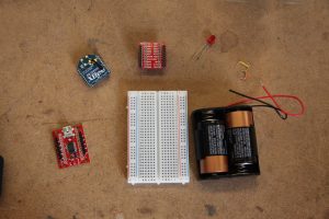
To hook up a LED to an XBee for PWM output, you'll need:
- XBee 802.15.4 Radio
- An LED
- Breadboard
- Jumper cables
- XBee Breakout Board - for your circuit.
- XBee Explorer USB - for programming your radio.
- A DC power source, 2.8 - 3.3V - We'll be using two C batteries in a battery holder from Radio Shack.
4) Wire up the Circuit
- Place the XBee adapter into the breadboard.
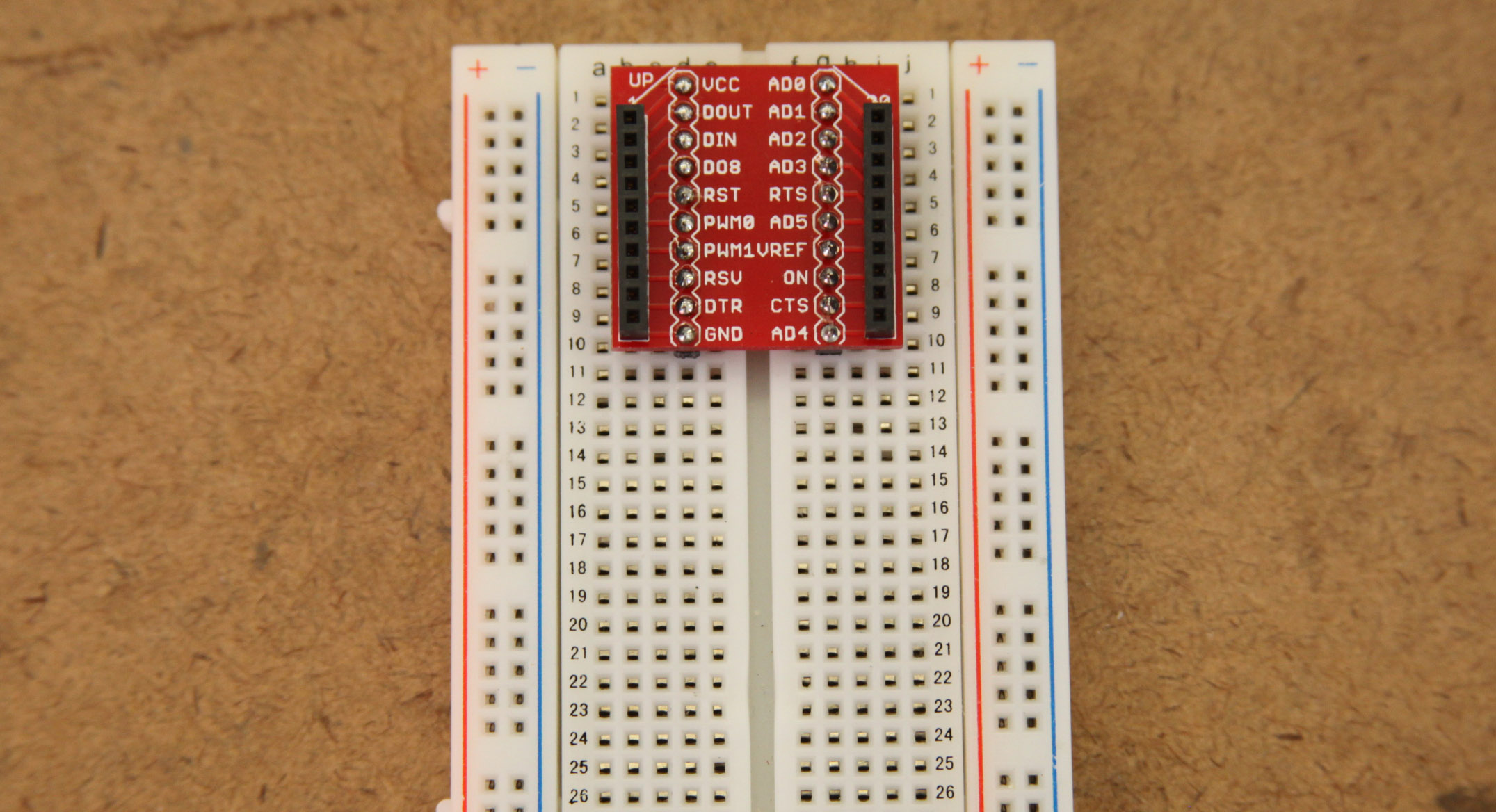
- Connect the VCC terminal of the XBee adapter to the positive rail and the ground terminal to the negative rail.
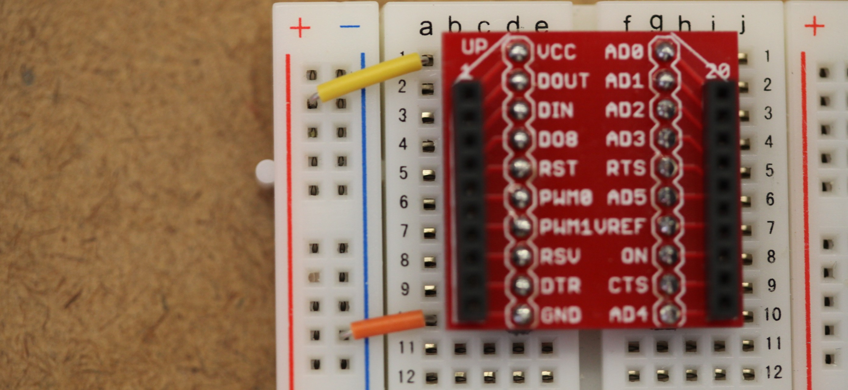
- Connect the LED's cathode side (the shorter lead) to the ground bus and the anode side (the longer lead) to the PWM0 pin, which is the 6th pin down on the left side.
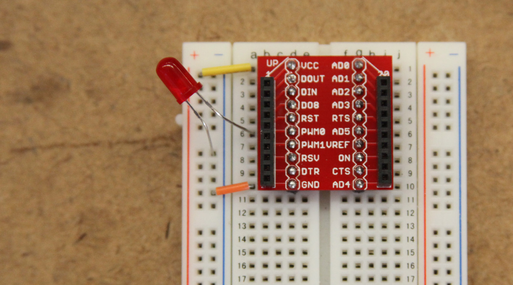
- Insert the XBee into the breakout board.
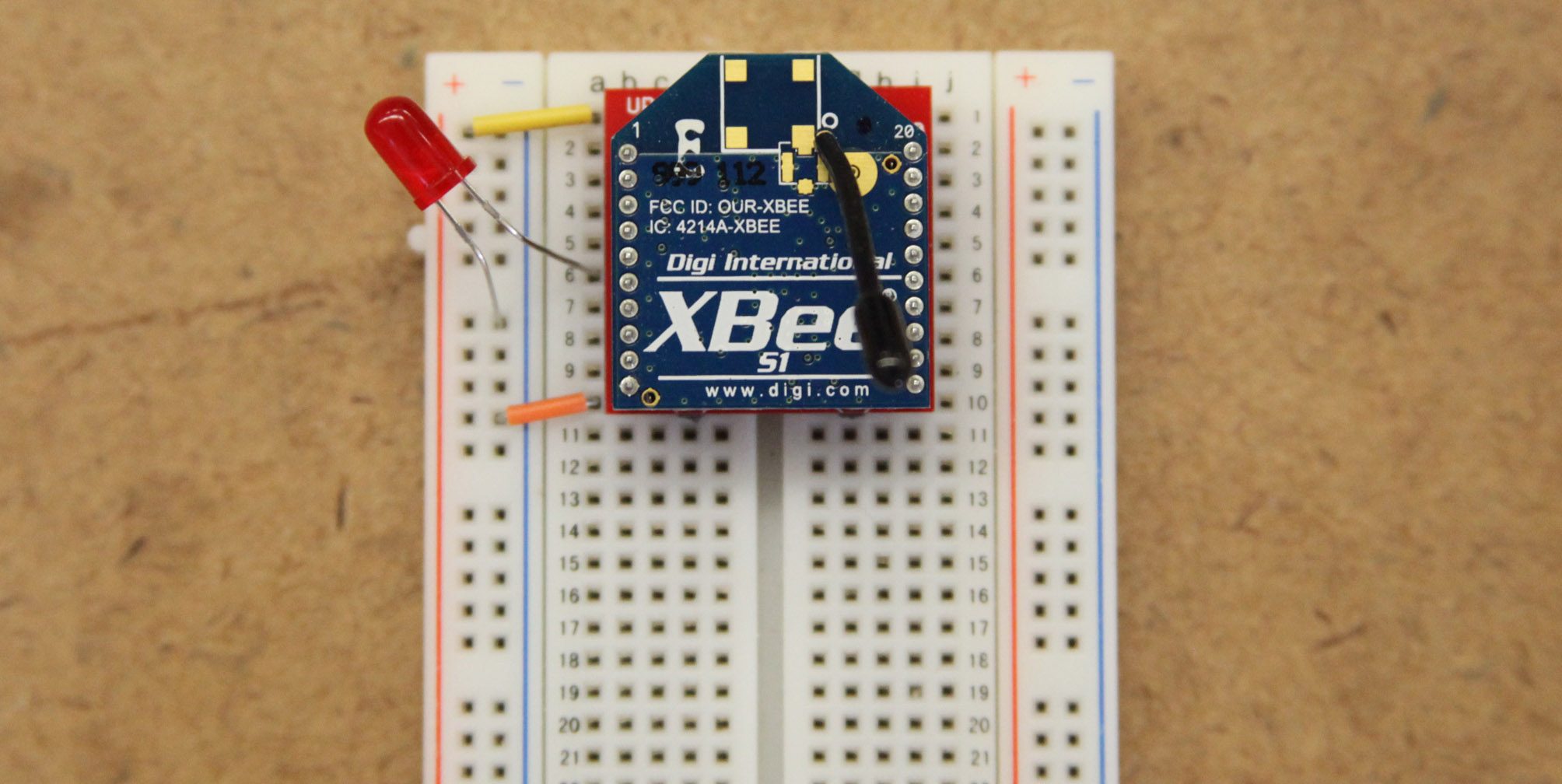
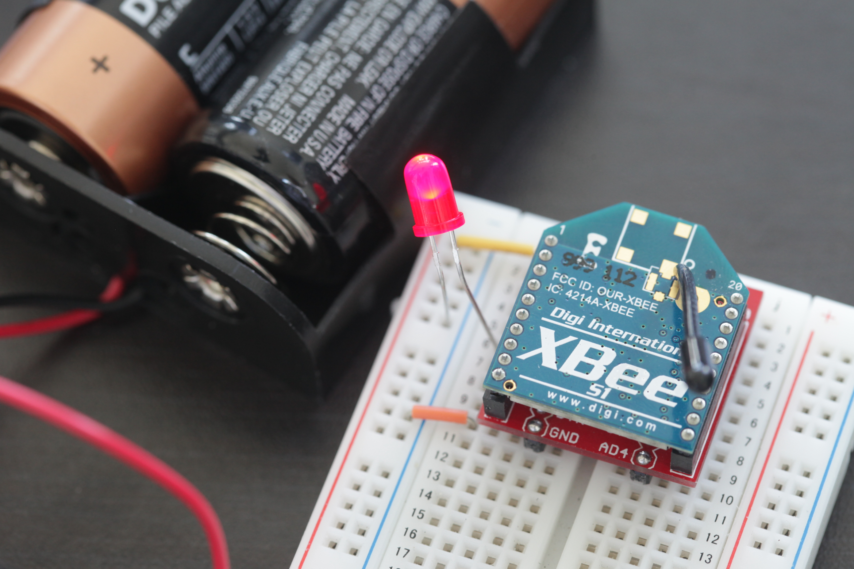
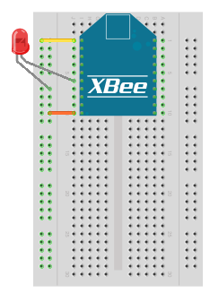
- Your circuit should look something like the diagram above.
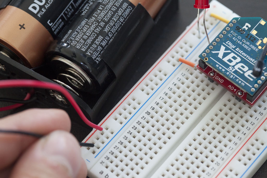
- Finally, connect the battery pack.
5) Use it!
Now that you know how to connect an LED to the PWM output of an XBee radio, take a look at our input tutorials for what can change the brightness of the LED. Just be sure that the the transmitter's address is set as the receiver's I/O input address setting (ATIA). The video above shows a wireless potentiometer connected to a wireless LED.