Replace XBee socket boards
To replace XBee socket boards, order interchangeable board(s) by part number:
| XBee device form-factor | Part number |
|---|---|
| Micro-mount (MMT) | XBEE-MP-MCRO-PCB |
| Surface-mount (SMT) | XBEE-MP-SMT-PCB |
| Through-hole (TH) | XBEE-MP-TH-PCB |
When you have the board(s):
- Remove the USB connector and power cable.
- Remove seven screws.
- Remove the plastic cover. You may need a thin knife blade or a flat-head screw driver to help pry off the plastic cover.
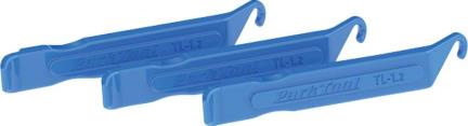
- Use the extraction levers shown in the following picture. They are XBee Multi Programmer PCB Extraction Levers.
This picture shows the location to insert the levers:

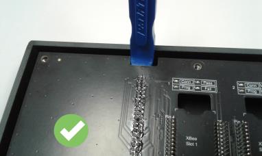
This picture shows a lever inserted correctly:
This picture shows a lever inserted incorrectly:

- Apply pressure such that the top board rises evenly, so that pins are not bent or damaged during the removal process. Ensure that the lever is not flexing the plastic housing more than a few millimeters; if so, the extraction lever is inserted too far.
WARNING! Lifting only one side at a time will bend the pins!
- Inspect the connectors for any damaged or bent pins.


- Insert the new board.
- Press firmly on the board next to the connectors such that the board seats evenly until touching the standoffs.

- Place the plastic cover on the XBee Multi Programmer again.
- Place and tighten the screws.
 PDF
PDF


