Wire the circuit
Build the sensor circuit using the XBee Development Board.
- Plug the temp sensor into three separate rows on the breadboard as shown. With the flat side facing you, the pins are numbered 1 to 3 from right to left.
- Connect a red jumper wire from a socket in the same row as pin 1 of the TMP36 to 3.3 volts power.
- Connect a black jumper wire so that pin 3 of the TMP36 is connected to GND (ground).
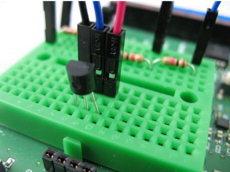
- Plug the four resistors into separate rows of the breadboard as shown in the following graphic. This forms a chain, with each resistor connecting the end of each other resistor on either side and scales the input down from 3.3 volt input to the 2.5 volt maximum of the XBee Wi-Fi's ADC.
- Connect a blue (or any other color) jumper wire so that the middle pin (2) of the TMP36 connects to the open end of the first resistor.
- Connect one end of a yellow (or any other color) jumper wire to the row where the first and second resistors meet. Connect the other end of this wire to the XBee's AD2 pin.
- Use a black wire to connect the open end of the fourth resistor to GND.

- Set the DIP switch for AD2 on the PCB to OFF to disconnect the soldered-on component.

The following image provides an example of how the board appears when you have finished connecting all the circuits:

 PDF
PDF


