XBIB-C SMT reference
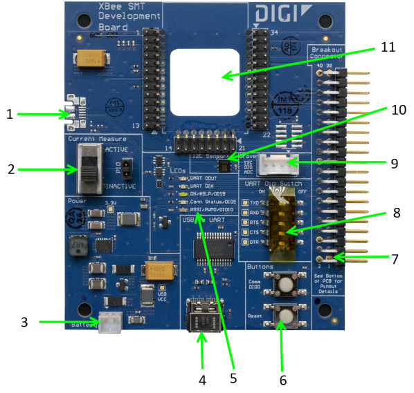
This picture shows the XBee-C SMT development board and the table that follows explains the callouts in the picture.
Note This board is sold separately.
|
Number |
Item |
Description |
|---|---|---|
|
1 |
Secondary USB (USB MICRO B) |
Secondary USB Connector for possible future use. Not used. |
|
2 |
Current Measure |
Large switch controls whether current measure mode is active or inactive. When inactive, current can freely flow to the VCC pin of the XBee. When active, the VCC pin of the XBee is disconnected from the 3.3 V line on the dev board. This allows current measurement to be conducted by attaching a current meter across the jumper P10. |
|
3 |
Battery Connector |
If desired, you can attach a battery to provide power to the development board. The voltage can range from 2 V to 5 V. The positive terminal is on the left. |
|
4 |
USB-C Connector |
Connects to your computer. This is connected to a USB to UART conversion chip that has the five UART lines passed to the XBee. The UART Dip Switch can be used to disconnect these UART lines from the XBee. |
|
5 |
LED indicator |
Red: UART DOUT (modem sending serial/UART data to host) Green: UART DIN (modem receiving serial/UART data from host) White: ON/SLP/DIO9 Blue: Connection Status/DIO5 Yellow: RSSI/PWM0/DIO10 |
|
6 |
User Buttons |
Comm DIO0 Button connects the Commissioning/DIO0 pin on the XBee Connector through to a 10 Ω resistor to GND when pressed.
RESET Button Connects to the RESET pin on the XBee Connector to GND when pressed. |
|
7 |
Breakout Connector |
This 40-pin connector can be used to connect to various XBee pins as shown on the silkscreen on the bottom of the board. |
|
8 |
UART Dip Switch |
This dip switch allows the user to disconnect any of the primary UART lines on the XBee from the USB to UART conversion chip. This allows for testing on the primary UART lines without the USB to UART conversion chip interfering. Push Dip switches to the right to disconnect the USB to UART conversion chip from the XBee. |
|
9 |
Grove Connector |
This connector can be used to attach I2C enabled devices to the development board. Note that I2C needs to be available on the XBee in the board to use this functionality. Pin 1: I2C_CLK/XBee DIO1 Pin2: I2C_SDA/XBee DIO11 Pin3: VCC Pin4: GND |
|
10 |
Temp/Humidity Sensor |
This as a Texas Instruments HDC1080 temperature and humidity sensor. This part is accessible through I2C. Be sure that the XBee that is inserted into the Dev Board has I2C if access to this sensor is desired. |
|
11 |
XBee Socket |
This is the socket for the XBee (SMT form factor) |
 PDF
PDF


