I/O data format
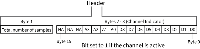
I/O data begins with a header. The first byte of the header defines the number of samples forthcoming. The last two bytes of the header (Channel Indicator) define which inputs are active. Each bit represents either a DIO line or ADC channel. The following figure illustrates the bits in the header.
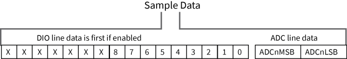
Sample data follows the header and the channel indicator frame determines how to read the sample data. If any of the DIO lines are enabled, the first two bytes are the DIO sample. The ADC data follows. ADC channel data is represented as an unsigned 10-bit value right-justified on a 16- bit boundary. The following figure illustrates the sample data bits.
 PDF
PDF


